Dieffematic EKOS M1/ECO
Dieffematic 230V Sliding Gate Control Unit User Manual
Model: EKOS M1/ECO
Adaptable to BFT Mizar 6 Alpha Systems
Introduction
This manual provides comprehensive instructions for the installation, operation, maintenance, and troubleshooting of the Dieffematic EKOS M1/ECO 230V Sliding Gate Control Unit. Please read this manual carefully before proceeding with any installation or operation to ensure safe and correct usage.
The Dieffematic EKOS M1/ECO is designed to manage sliding gate automation systems, offering reliable control and compatibility with various gate motors, including those adaptable to BFT Mizar 6 Alpha systems. It also includes two EQUO remote controls for convenient operation.
Product Overview
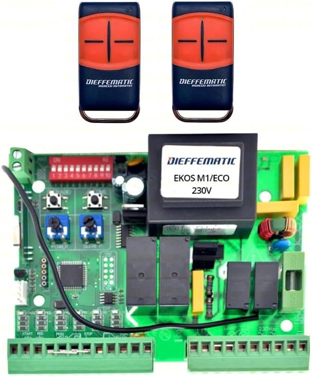
Figure 1: Dieffematic EKOS M1/ECO 230V Sliding Gate Control Unit and included remote controls. The image displays the green circuit board of the control unit with various components, including relays, terminals, and DIP switches. Two black and orange remote controls are shown above the circuit board.
The Dieffematic EKOS M1/ECO control unit is a robust electronic board designed for the precise control of 230V sliding gate motors. It features adjustable parameters for motor power, speed, and operational logic. The package includes two EQUO remote controls, pre-programmed for immediate use with the control unit.
Setup and Installation
Important Safety Information: Installation must be performed by qualified personnel in compliance with local electrical codes and safety regulations. Disconnect power before any installation or maintenance procedures.
1. Mounting the Control Unit
- Choose a dry, protected location, preferably inside a weatherproof enclosure.
- Ensure adequate ventilation to prevent overheating.
- Mount the unit securely using appropriate fasteners.
2. Electrical Connections
Refer to the wiring diagram provided with the product for detailed connection points. Below are general guidelines:
- Power Supply (230V AC): Connect the main power supply to the designated terminals (L, N, Earth). Ensure proper grounding.
- Motor Connections: Connect the gate motor's common, open, and close wires to the respective motor terminals.
- Safety Devices: Connect photocells, safety edges, and emergency stop buttons to their dedicated safety input terminals. These are crucial for safe operation.
- Command Inputs: Connect external command devices such as key switches, push buttons, or access control systems to the 'Start', 'Pedestrian', or 'Stop' inputs as required.
- Accessories: Connect flashing lights, courtesy lights, or electric locks to the auxiliary output terminals.
3. Initial Configuration (DIP Switches and Trimmers)
The control unit features DIP switches and potentiometers (trimmers) for initial setup and fine-tuning.
- DIP Switches: Configure operational modes such as automatic closing, condominium mode, soft start/stop, and motor direction. Consult the specific DIP switch configuration table in the product's detailed wiring diagram.
- Trimmers (Potentiometers): Adjust parameters like motor power (FORCE), opening/closing speed (SPEED), and pause time for automatic closing (PAUSE).
Note: Exact labeling and function of DIP switches and trimmers may vary slightly. Always refer to the specific diagram included with your product.
Operating Instructions
1. Remote Control Operation
The included EQUO remote controls are pre-programmed. Pressing the designated button on the remote will initiate the gate's movement (open/close/stop cycle).
- Single Button Mode: Each press cycles the gate: Open → Stop → Close → Stop → Open.
- Dedicated Buttons (if applicable): Some remotes may have separate buttons for Open, Close, and Stop.
2. Manual Operation
In case of power failure or system malfunction, the gate can be operated manually. Locate the manual release mechanism on your gate motor (usually a key-operated lever or knob) and disengage it to move the gate by hand.
3. Safety Features
The control unit is designed with several safety features:
- Photocells: If the photocell beam is interrupted during closing, the gate will stop and reverse.
- Obstacle Detection: The unit can detect obstacles during movement and reverse the gate to prevent damage or injury.
- Emergency Stop: An emergency stop input allows for immediate cessation of gate movement.
Maintenance
Regular maintenance ensures the longevity and safe operation of your gate automation system.
1. General Checks (Monthly)
- Inspect the gate's mechanical components (wheels, tracks, hinges) for wear or damage.
- Clean photocell lenses to ensure proper function.
- Check all electrical connections for tightness and signs of corrosion.
- Test safety devices (photocells, safety edges) by intentionally triggering them during gate operation.
2. Control Unit Care
- Keep the control unit enclosure clean and free from dust, insects, and moisture.
- Do not spray water directly onto the unit.
- Ensure the enclosure is properly sealed to protect against environmental elements.
Note: For any complex repairs or internal component replacement, contact a qualified technician.
Troubleshooting
This section provides solutions to common issues. For problems not listed here, contact technical support.
| Problem | Possible Cause | Solution |
|---|---|---|
| Gate does not move. | No power; Blown fuse; Safety device activated; Remote control battery low. | Check power supply; Replace fuse; Check photocells/safety edges for obstructions; Replace remote battery. |
| Gate opens but does not close. | Photocells obstructed or misaligned; Automatic closing disabled. | Clean and align photocells; Check DIP switch settings for automatic closing. |
| Gate stops unexpectedly. | Obstacle detected; Motor overheating; Limit switch issue. | Remove obstruction; Allow motor to cool; Check limit switch connections/adjustment. |
| Remote control not working. | Battery dead; Out of range; Not programmed correctly. | Replace battery; Move closer to receiver; Re-program remote (refer to programming instructions). |
Specifications
| Feature | Detail |
|---|---|
| Model | EKOS M1/ECO |
| Power Supply | 230V AC |
| Compatibility | Sliding gate motors (adaptable to BFT Mizar 6 Alpha systems) |
| Included Remotes | 2 x EQUO Remote Controls |
| Safety Inputs | Photocell, Emergency Stop, Safety Edge |
| Adjustable Parameters | Motor Power, Speed, Pause Time, Operational Logic (via DIP switches) |
| ASIN | B07ZKM72NC |
| Manufacturer Reference | 264387266542 |
Warranty and Support
For warranty information, please refer to the documentation provided with your purchase or contact your retailer. Dieffematic products are designed for durability and performance.
For technical support, troubleshooting assistance beyond this manual, or spare parts, please contact Dieffematic customer service or your authorized dealer. Ensure you have your product model (EKOS M1/ECO) and purchase details ready when contacting support.
Contact Information:
- Please refer to the official Dieffematic website or your purchase invoice for the most up-to-date contact details.