1. Introduction
This manual provides essential information for the safe and effective use of the daier 12V 100A 4S BMS Protection Board, Model E1152. This Battery Management System (BMS) is designed for 4-series 12V LiFePO4 battery packs, offering critical protection functions to ensure battery longevity and safety. It includes features such as overcharge protection, over-discharge protection, short circuit protection, over-current protection, and cell balancing.
2. Key Features
The daier 12V 100A 4S BMS Protection Board offers several critical features for managing LiFePO4 battery packs:
- Comprehensive Protection: Integrates overcharge, over-discharge, short circuit, and over-current protection mechanisms to safeguard the battery and connected devices.
- Cell Balancing: Equipped with a balance function to ensure each battery cell is charged uniformly, optimizing pack performance and lifespan.
- High Current Capability: Supports a continuous discharging current of up to 100A and an instantaneous discharge current of up to 150A.
- Dedicated for LiFePO4: Specifically designed for 4-series 12V LiFePO4 battery configurations.
- Easy Integration: Comes with a 5P-250mm wire for convenient connection to battery cells.
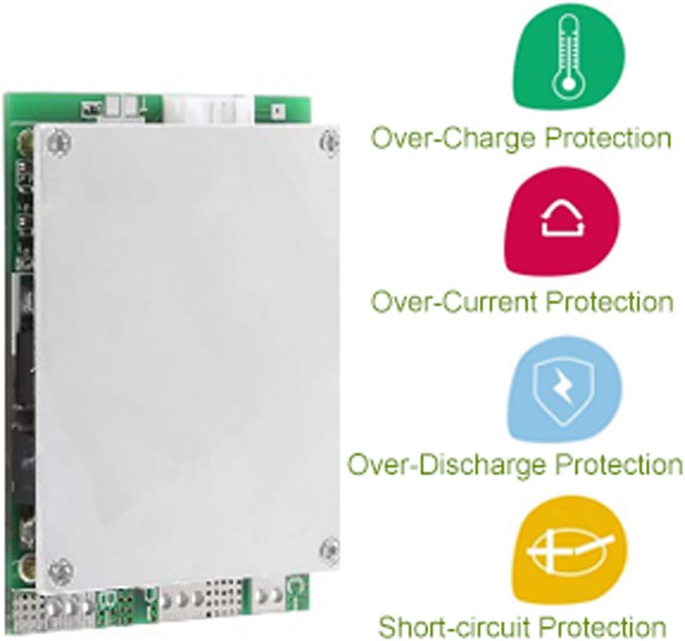
Figure 1: Visual representation of the BMS protection features.

Figure 2: daier 4S BMS Protection Board with balance wires.
3. Setup and Wiring Instructions
Proper wiring is critical for the correct operation and safety of the BMS and your battery pack. Refer to the wiring diagram below and follow these steps carefully.

Figure 3: Wiring Diagram for daier 4S BMS.
- Battery Connections (B- and B+):
- Connect the main negative terminal of your 4-series LiFePO4 battery pack to the B- terminal on the BMS.
- Connect the main positive terminal of your 4-series LiFePO4 battery pack to the B+ terminal on the BMS.
- Balance Wire Connections:
The BMS comes with a 5-pin balance wire harness. Connect these wires to the individual cell terminals as follows:
- Connect the first balance wire (often black or the lowest voltage wire) to the negative terminal of the first cell (B0).
- Connect the second balance wire to the positive terminal of the first cell (B1).
- Connect the third balance wire to the positive terminal of the second cell (B2).
- Connect the fourth balance wire to the positive terminal of the third cell (B3).
- Connect the fifth balance wire (often red or the highest voltage wire) to the positive terminal of the fourth cell (B4).
- Ensure all balance wires are connected in the correct sequence to prevent damage.
- Charging/Output Connections (P- and P+):
- Connect the negative terminal of your charger and load to the P- terminal on the BMS.
- Connect the positive terminal of your charger and load to the P+ terminal on the BMS.
- Verification: Double-check all connections for polarity and sequence before applying power. Incorrect wiring can lead to damage to the BMS, batteries, or connected devices.
4. Operating Principles
The BMS continuously monitors the voltage, current, and temperature of the battery pack to ensure safe operation. Its primary functions include:
- Overcharge Protection: Prevents individual cells from being charged beyond their safe voltage limit (3.75V ± 0.05V detection, 3.65V ± 0.1V release). This protects against cell degradation and potential hazards.
- Over-discharge Protection: Disconnects the load if any cell's voltage drops below a safe minimum (2.0V ± 0.1V detection, 2.25V ± 0.1V release), preventing irreversible damage to the battery.
- Over-current Protection: Limits the discharge current to prevent damage to the battery and BMS from excessive loads (200A ± 10A detection, releases upon load cut).
- Short Circuit Protection: Immediately cuts off output in the event of a short circuit (detection delay 250µS, releases upon load cut), protecting the entire system from severe damage.
- Cell Balancing: During charging, the balance function (36mA ± 5mA current) ensures that all cells within the pack reach the same voltage level, maximizing the usable capacity and lifespan of the battery pack.
5. Maintenance
To ensure the longevity and reliable performance of your daier BMS, consider the following maintenance guidelines:
- Regular Inspection: Periodically inspect all wiring connections for tightness and signs of corrosion or damage.
- Environmental Conditions: Operate the BMS within its specified working temperature range (-30°C to +80°C) and avoid exposure to excessive moisture or dust.
- Cleaning: If necessary, gently clean the board with a soft, dry brush to remove any accumulated dust. Do not use liquids or abrasive cleaners.
- Storage: If storing the battery pack with the BMS for an extended period, ensure the batteries are at a suitable storage voltage (typically around 50% State of Charge) to prevent over-discharge.
6. Troubleshooting
If you encounter issues with your BMS, consider the following common troubleshooting steps:
- No Output Voltage:
- Check all wiring connections, especially the main battery terminals (B-, B+) and output terminals (P-, P+).
- Verify that the battery pack voltage is within the normal operating range (above over-discharge protection threshold).
- Ensure no short circuit is present on the output. The BMS will cut output in case of a short.
- Check individual cell voltages. If any cell is significantly lower than others, the BMS might have triggered over-discharge protection.
- BMS Gets Hot During Operation:
- Excessive heat can indicate that the load current is too high for the BMS's continuous rating. Reduce the load.
- Ensure adequate ventilation around the BMS.
- Verify that the BMS is correctly rated for your application's current demands.
- Battery Cells Are Not Balancing:
- Confirm that all balance wires are correctly connected to their respective cell terminals.
- Balancing typically occurs during charging when cells reach a certain voltage. Ensure the battery pack is being charged.
- Significant cell voltage differences may take a long time to balance with passive balancing.
- Charging Stops Prematurely:
- Check if any cell has reached the overcharge protection voltage.
- Verify the charger's output voltage and current are appropriate for a 4S LiFePO4 pack.
If issues persist after performing these checks, contact customer support for further assistance.
7. Specifications
| Parameter | Value |
|---|---|
| Continuous Discharging Current | 100A (MAX) |
| Instantaneous Discharge Current | 150A |
| Charging Voltage | 15V |
| Charging Current | 10A (MAX) |
| Inner Resistance | ≤25mΩ |
| Working Current | ≤20uA |
| Sleep Current (Over-discharge) | ≤10uA |
| Working Temperature Range | -30°C to +80°C |
| Over-charge Detect Voltage | 3.75V ± 0.05V |
| Over-charge Release Voltage | 3.65V ± 0.1V |
| Over-discharge Detect Voltage | 2.0V ± 0.1V |
| Over-discharge Release Voltage | 2.25V ± 0.1V |
| Balance Current | 36mA ± 5mA |
| Model Number | E1152 |
8. Warranty and Support
For warranty information or technical support, please refer to the retailer or manufacturer's official website. Keep your purchase receipt for any warranty claims. For specific inquiries regarding the daier 12V 100A 4S BMS Protection Board (Model E1152), please contact daier customer service.