ProIcWorld SDM630Modbus
Instruction Manual
SDM630 Modbus RS485 Din Rail KWH Three Phase Energy Meter
Model: SDM630Modbus | Brand: ProIcWorld
1. Introduction
This manual provides comprehensive instructions for the installation, operation, and maintenance of the SDM630 Modbus RS485 Din Rail KWH Three Phase Energy Meter. This device is designed to measure and display characteristics of single-phase two-wire, three-phase three-wire, and three-phase four-wire electrical supplies. It accurately measures voltage, frequency, current, power, active and reactive energy (imported or exported), and energy in kWh and kVArh. The SDM630Modbus supports direct connection up to 100A, simplifying installation and reducing the need for external current transformers (CTs).
2. Safety Information
Please read and understand all safety instructions before installing or operating the device. Failure to comply with these instructions may result in electric shock, fire, or serious injury.
- Installation and maintenance should only be performed by qualified personnel.
- Ensure all power is disconnected before making any electrical connections.
- Verify correct wiring and polarity to prevent damage to the device or electrical system.
- Do not operate the device if it appears damaged.
- The device is designed for indoor use in a dry environment. Avoid exposure to moisture or extreme temperatures.
3. Product Overview
The SDM630Modbus is a compact, DIN rail-mountable energy meter featuring a clear LCD with blue backlight for easy reading. It includes built-in pulse and Modbus outputs for integration into larger systems.
3.1. Key Features
- Measures kWh, kVArh, KW, kVAr, kVA, Power Factor (PF), Frequency (Hz), Demand (dmd), Voltage (V), Current (A).
- Bi-directional measurement (Import & Export).
- Two pulse outputs.
- Modbus RTU communication via RS485.
- 35mm DIN rail mounting.
- 100A direct connection capability.
- LCD with blue backlight, max reading 999999.99 kWh.
3.2. Device Components

Figure 1: Front view of the SDM630 Modbus energy meter, showing the LCD display, navigation buttons (U/I, M, P, E), and status indicators. The display currently shows 0000 kWh and 031.4.

Figure 2: Another front view of the SDM630 Modbus energy meter, highlighting the LCD display with a different reading of 0000 kWh and 119.2. This view emphasizes the clear blue backlight.

Figure 3: Angled view of the SDM630 Modbus energy meter, providing a perspective of both the front display and the side profile, including the terminal block for electrical connections at the bottom.
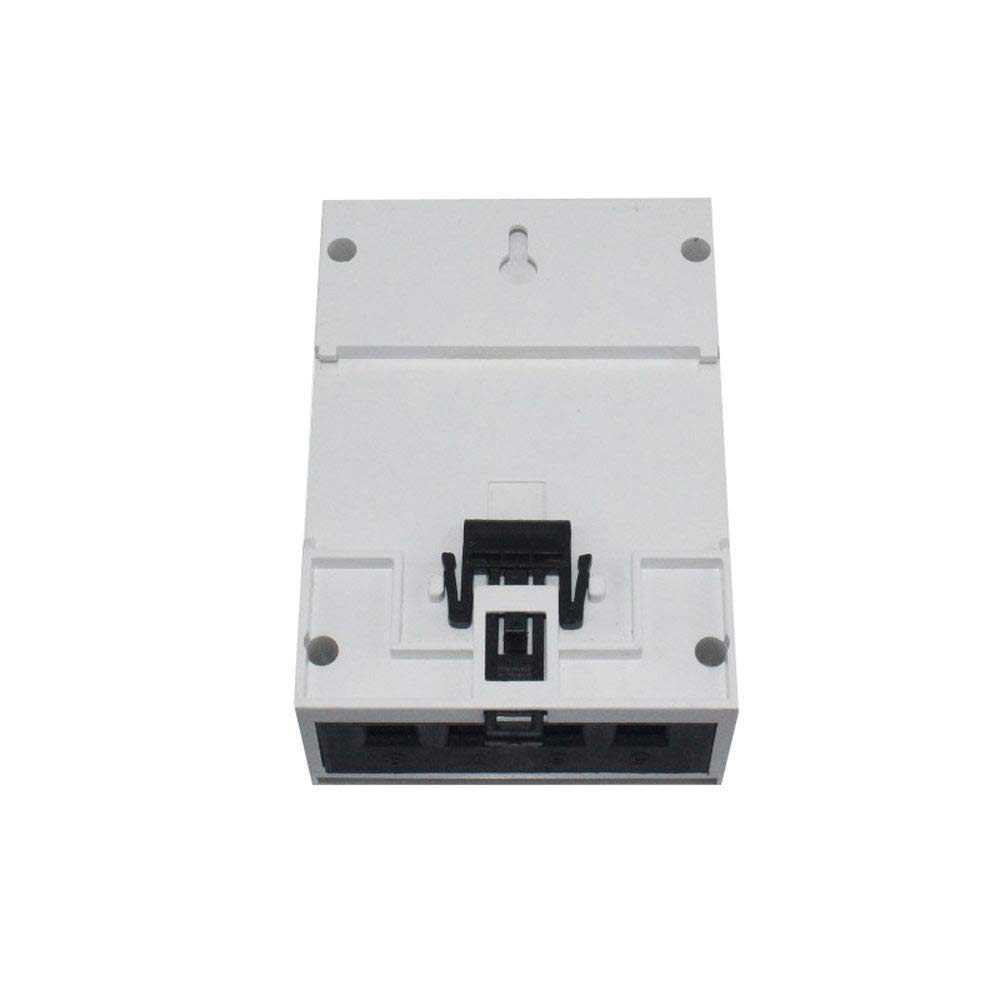
Figure 4: Back view of the SDM630 Modbus energy meter, illustrating the integrated DIN rail clip for secure mounting and additional mounting points.
4. Specifications
| Parameter | Value |
|---|---|
| Voltage AC (Un) | 230/400V |
| Base Current (Ib) | 10A |
| Max. Current (Imax) | 100A |
| Mini Current (Imin) | 0.5A |
| Starting Current | 0.4% of Ib |
| Power Consumption | <2W/10VA |
| Frequency | 50/60Hz (±10%) |
| AC Voltage Withstand | 4KV for 1 minute |
| Impulse Voltage Withstand | 6KV-1.2uS waveform |
| Overcurrent Withstand | 30Imax for 0.01s |
| Pulse Output Rate | 1000imp/kWh (default), configurable to 100/10/1 imp/kWh/kVArh |
| Display | LCD with blue backlight, Max. Reading 999999.99kWh |
| Mounting | 35mm DIN rail |
| Communication | Modbus RTU (RS485) |
5. Setup and Installation
The SDM630Modbus is designed for easy installation on a standard 35mm DIN rail.
5.1. Wiring Diagram (General Guidance)
Note: A detailed wiring diagram is typically provided with the physical product. The following is general guidance. Always refer to the specific diagram included with your meter.
- Power Supply: Connect the main voltage supply to the designated terminals (e.g., L1, L2, L3, N). Ensure correct phase sequence for three-phase systems.
- Current Inputs: For direct connection, route the load current through the meter's internal current paths (terminals for L1, L2, L3 current input/output). The meter supports up to 100A direct connection.
- RS485 Modbus: Connect the RS485 A and B lines to the corresponding terminals for Modbus communication. Ensure proper termination if it's the end of a bus.
- Pulse Outputs: Connect external devices (e.g., PLCs, data loggers) to the pulse output terminals if energy pulse signals are required.
- Grounding: Ensure proper grounding of the electrical system.
After wiring, secure the meter firmly on the DIN rail. Double-check all connections before restoring power.
6. Operating Instructions
Once powered, the meter's LCD will illuminate. The display cycles through various measurement parameters.
6.1. Navigating the Display
The meter typically has navigation buttons (e.g., "U/I", "M", "P", "E" as seen in Figure 1) to scroll through different parameters and access configuration menus.
- Scrolling: Use the arrow buttons (often labeled with up/down arrows or 'P' for Page/Parameter) to cycle through displayed values such as voltage, current, power, frequency, and energy readings (kWh, kVArh).
- Menu Access: A dedicated button (e.g., 'M' for Menu) or a combination of buttons may be used to enter the configuration menu. Access to this menu is usually password-protected.
- Resetting: Certain parameters, like maximum demand, can be reset via the menu. Refer to the specific product manual for reset procedures and password details.
6.2. Modbus Communication
The SDM630Modbus supports Modbus RTU protocol over RS485. This allows for remote reading of all measured parameters and configuration of certain settings.
- Baud Rate: Common baud rates include 9600, 19200, etc. This can usually be configured via the meter's menu or Modbus commands.
- Parity: N81 (No parity, 8 data bits, 1 stop bit) is common.
- Slave ID: Each meter on a Modbus network requires a unique slave ID.
- Register Map: A detailed Modbus register map is essential for communication and is typically provided in the full technical manual. This map lists the addresses for all measurable parameters and configurable settings.
7. Maintenance
The SDM630Modbus energy meter is designed for long-term, maintenance-free operation under normal conditions.
- Cleaning: Periodically clean the meter's exterior with a soft, dry cloth. Do not use abrasive cleaners or solvents.
- Inspection: Regularly inspect wiring connections to ensure they are secure and free from corrosion or damage.
- Environment: Ensure the operating environment remains within specified temperature and humidity ranges to prevent premature failure.
- Firmware: Firmware updates are generally not user-serviceable. Contact the manufacturer if an update is deemed necessary.
No user-serviceable parts inside. Do not attempt to open the casing.
8. Troubleshooting
This section provides solutions to common issues you might encounter.
| Problem | Possible Cause | Solution |
|---|---|---|
| Meter display is blank. | No power supply to the meter. | Check input voltage connections and ensure power is supplied to the meter's terminals. |
| Incorrect readings (voltage, current, power). | Incorrect wiring or phase sequence. | Verify all wiring connections against the product's specific wiring diagram. Ensure correct phase sequence for three-phase systems. |
| Modbus communication failure. | Incorrect RS485 wiring (A/B reversed), incorrect baud rate/parity, incorrect slave ID, bus termination issues. | Check RS485 A and B connections. Verify Modbus settings (baud rate, parity, slave ID) match the master device. Ensure proper bus termination if applicable. |
| Energy (kWh) reading not increasing. | No load connected or current inputs incorrectly wired. | Ensure there is an active load connected to the circuit being measured. Re-check current input wiring. |
If the problem persists after attempting these solutions, please contact customer support.
9. Warranty and Support
For warranty information and technical support, please refer to the documentation provided with your purchase or visit the official ProIcWorld website.
Manufacturer: ProIcWorld
Model: SDM630Modbus
ASIN: B07YY6QWHF
Related Documents - SDM630Modbus
 |
Eastron SDM630Modbus Smart Meter: Modbus Protocol Implementation Guide This technical document details the Modbus RTU protocol implementation for the Eastron SDM630Modbus Smart Meter, covering RS485 communication, register mapping, message formats, and error handling for system integration. |
 |
SigenStor Home Energy Storage System Installation Guide with Checkwatt CM10 Comprehensive installation and user guide for the Sigenergy SigenStor Home Three-phase energy storage system, including integration with the Checkwatt CM10 device. Covers safety precautions, system components, wiring diagrams, and app operation. |
 |
Eastron SDM630MODBUS Energiemeter - Specificaties en Details Technische specificaties en productomschrijving van de Eastron SDM630MODBUS 100A 3-fase energiemeter met Modbus RS485 interface. |
 |
Sigenergy TOP150 FAQ: Comprehensive Guide to Sigen Products Explore the Sigenergy TOP150 FAQ for detailed answers on SigenStor, inverters, gateways, batteries, and EV chargers. This guide covers installation, operation, and troubleshooting for Sigenergy's energy solutions. |
 |
SigenStor Home Installation Guide - Three-phase System A1 Comprehensive installation guide for the Sigenergy SigenStor Home Three-phase System A1, covering system setup, wiring, site requirements, and post-installation procedures for trained electrical personnel. |
Ask a question about this manual
Ask about setup, troubleshooting, compatibility, parts, safety, or missing instructions. Manuals+ will review the question and use this page’s manual context to help answer it.