
Teltonika FMB140
Teltonika FMB140 User Manual
GNSS/GSM/BLE Terminal with CAN Bus Support
1. Introduction
This user manual provides comprehensive instructions for the installation, operation, and maintenance of the Teltonika FMB140 GNSS/GSM/BLE terminal. The FMB140 is an advanced tracking device with integrated CAN bus data reading capabilities, designed for various fleet management and vehicle tracking applications. Please read this manual carefully before using the device to ensure proper functionality and safety.
2. Product Overview
The Teltonika FMB140 is a compact and reliable GNSS/GSM/BLE terminal equipped with an internal Li-ion battery and advanced features for vehicle data acquisition. It supports GNSS (Global Navigation Satellite System) for precise positioning, GSM for communication, and Bluetooth Low Energy (BLE) for connectivity with various sensors and accessories. Its key feature is the ability to read CAN bus data from vehicles, providing valuable insights into vehicle performance and status.

Figure 2.1: Front view of the Teltonika FMB140 device, showing its compact design and branding.
2.1. Key Features
- GNSS (GPS, GLONASS, GALILEO, BEIDOU) positioning
- GSM/GPRS connectivity
- Bluetooth 4.0 LE for external devices
- CAN bus data reading (J1939, J1708, FMS)
- Internal Li-ion battery (3.7V, 170mAh)
- Internal GNSS and GSM antennas
- Digital Inputs/Outputs, Analog Inputs
- 1-Wire data interface
- Over-the-Air (OTA) updates
3. Safety Information
Please observe the following safety precautions to prevent damage to the device and ensure safe operation:
- Do not disassemble or modify the device.
- Ensure proper power supply voltage (10-30V DC) as specified.
- Avoid exposing the device to extreme temperatures, humidity, or direct sunlight.
- Keep the device away from strong magnetic fields.
- Disconnect power before performing any wiring or maintenance.
- Installation should be performed by qualified personnel.
4. Package Contents
Verify that all items are present in the package:
- Teltonika FMB140 device
- Power/data cable (may be sold separately depending on region/bundle)
- Quick Start Guide (digital version available online)
5. Setup and Installation
5.1. SIM Card Insertion
- Locate the SIM card slot on the device.
- Insert a valid Micro-SIM card with an active data plan. Ensure the SIM card is inserted correctly according to the diagram on the device or in the quick start guide.
- Close the SIM card cover securely.
5.2. Wiring Diagram and Connections
The FMB140 features a 2x6 socket for power, digital inputs/outputs, analog inputs, and 1-Wire data, as well as a dedicated CAN bus connector. Refer to the diagram below for pin assignments.
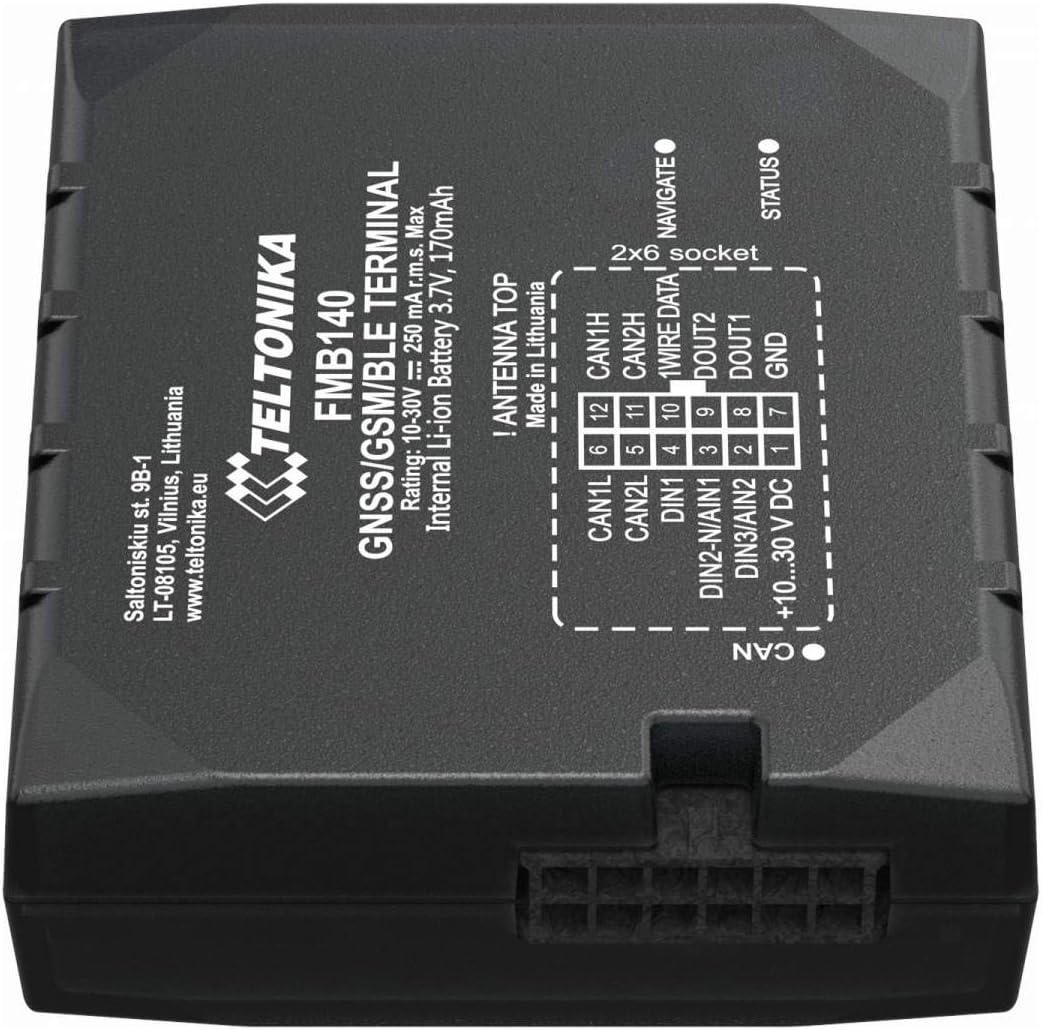
Figure 5.1: Detailed view of the Teltonika FMB140's 2x6 socket pinout and CAN bus connector, indicating power, I/O, and data lines.
| Pin No. | Description | Function |
|---|---|---|
| 1 | +10...30 V DC | Power Supply Input |
| 2 | DIN3/AIN2 | Digital Input 3 / Analog Input 2 |
| 3 | DIN2-N/AIN1 | Digital Input 2 (Negative) / Analog Input 1 |
| 4 | DIN1 | Digital Input 1 |
| 5 | CAN2L | CAN Bus 2 Low |
| 6 | CAN1L | CAN Bus 1 Low |
| 7 | GND | Ground |
| 8 | DOUT1 | Digital Output 1 |
| 9 | DOUT2 | Digital Output 2 |
| 10 | 1WIRE DATA | 1-Wire Data Interface |
| 11 | CAN2H | CAN Bus 2 High |
| 12 | CAN1H | CAN Bus 1 High |
Power Connection: Connect the +10...30V DC wire to the vehicle's positive power source and GND to the vehicle's ground. Ensure a fuse is installed on the positive power line.
CAN Bus Connection: Connect CAN1H/CAN2H and CAN1L/CAN2L to the vehicle's CAN bus lines. Consult the vehicle's wiring diagram for correct CAN bus access points.
6. Operating the Device
6.1. Initial Power-Up and Status Indicators
Once powered, the device will initiate. Observe the LED indicators for status:
- NAVIGATE LED: Indicates GNSS status. Solid green when GPS fix is acquired.
- STATUS LED: Indicates GSM/GPRS status. Flashing indicates network activity, solid indicates registered.
6.2. Configuration
The FMB140 can be configured using Teltonika Configurator software via USB or remotely via FOTA (Firmware Over The Air) or SMS commands. Bluetooth connectivity also allows for configuration via a mobile application.

Figure 6.1: System block diagram of the Teltonika FMB140, illustrating its various interfaces and functionalities including configuration options.
6.3. Data Transmission
The device collects data from GNSS, CAN bus, and connected sensors, then transmits it to a server via GPRS. Data transmission parameters are configured through the Teltonika Configurator.
7. Maintenance
The Teltonika FMB140 is designed for minimal maintenance. However, regular checks are recommended:
- Keep the device clean and free from dust and debris.
- Ensure all cable connections are secure and free from damage.
- Periodically check for firmware updates to ensure optimal performance and access to new features.
- Avoid exposing the device to water or excessive moisture.
8. Troubleshooting
| Problem | Possible Cause | Solution |
|---|---|---|
| Device not powering on | No power supply; Incorrect wiring; Blown fuse. | Check power connections; Verify voltage; Replace fuse. |
| No GNSS fix (NAVIGATE LED off/flashing) | Poor satellite signal; Device indoors; Antenna obstruction. | Move device to open area; Ensure clear sky view. |
| No GSM network (STATUS LED off/flashing rapidly) | No SIM card; Invalid SIM; No network coverage; Incorrect APN settings. | Insert/check SIM; Verify network coverage; Configure APN. |
| No CAN bus data | Incorrect CAN wiring; Vehicle CAN bus inactive; Incorrect CAN settings. | Verify CAN connections; Ensure vehicle ignition is on; Check CAN configuration in software. |
If the problem persists after attempting these solutions, please contact Teltonika support.
9. Specifications
| Feature | Detail |
|---|---|
| Model Number | FMB140 |
| Brand | Teltonika |
| Dimensions (Packaging) | 18 x 15 x 4 cm |
| Weight (Item) | 220 g |
| Power Supply | 10-30 V DC |
| Internal Battery | 3.7V, 170mAh Li-ion |
| Connectivity | GNSS, GSM, Bluetooth 4.0 LE |
| Interfaces | CAN Bus (2x), Digital Inputs (3), Analog Inputs (2), Digital Outputs (2), 1-Wire, USB |
| Internal Memory | 128MB |
| Operating Temperature | -40°C to +85°C |
10. Warranty and Support
10.1. Warranty Information
Teltonika provides a standard manufacturer's warranty for the FMB140 device. Please refer to the official Teltonika website or your point of purchase for detailed warranty terms and conditions. Keep your proof of purchase for warranty claims.
10.2. Technical Support
For technical assistance, troubleshooting, or further information regarding the Teltonika FMB140, please visit the official Teltonika support portal or contact their authorized distributors. Comprehensive documentation, FAQs, and firmware updates are available on the Teltonika website: www.teltonika-networks.com/support/
Related Documents - FMB140
 |
Teltonika FMB140 GNSS/GSM/Bluetooth Tracker - Overview, Datasheet, Manuals, Drivers Detailed overview of the Teltonika FMB140, a versatile GNSS/GSM/Bluetooth tracker with CAN chip. Access datasheets, user manuals, firmware, drivers, and support resources. |
 |
Teltonika FMC640: General Description and Technical Specifications Detailed overview of the Teltonika FMC640, a professional 4G/LTE, GNSS, and Bluetooth vehicle tracking device. Covers package contents, cellular and GNSS features, hardware specifications, interfaces, special features, technical details, battery information, and electrical characteristics. |
 |
Teltonika FMM125 Quick Manual User manual for the Teltonika FMM125 Advanced CATM1/GSM/GNSS/BLE terminal, providing instructions for installation, configuration, wiring, and technical specifications. |
 |
Teltonika FMB2YX User Manual: GPS/GSM/BLE Terminal Guide Comprehensive user manual for the Teltonika FMB2YX device. Learn about its features, installation, configuration, and operation for GPS tracking, GSM communication, and BLE connectivity. |
 |
Teltonika FMM130 Quick Manual: Setup, Configuration, and Specifications A concise guide to the Teltonika FMM130 advanced CAT M1/GSM/GNSS/BLE terminal, covering setup, configuration, wiring, technical specifications, safety, and certifications. |
 |
FMM125 CAN Adapters: Installation, Configuration, and Data Flags Guide Comprehensive guide for installing and configuring Teltonika FMM125 CAN adapters (LV-CAN200, ALL-CAN300, CAN-CONTROL, ECAN01, ECAN02). Covers connection steps, program number selection via SMS and Teltonika Configurator, software updates, and an overview of CAN adapter state flags. |
Ask a question about this manual
Ask about setup, troubleshooting, compatibility, parts, safety, or missing instructions. Manuals+ will review the question and use this page’s manual context to help answer it.