1. Introduction
This manual provides essential information for the safe and effective installation, operation, and maintenance of the Merlin Gerin Masterpact MP16H1 Circuit Breaker. This device is designed for high-current electrical protection in industrial and commercial applications, featuring a 1600 Amp rating and LSI (Long-time, Short-time, Instantaneous) trip unit functionality.
Please read this manual thoroughly before any interaction with the circuit breaker to ensure proper handling and to prevent potential hazards.
2. Important Safety Information
WARNING: Risk of electric shock, explosion, or arc flash.
- Installation, operation, and maintenance must be performed by qualified personnel only.
- Always de-energize and lockout/tagout the power supply before working on or near the circuit breaker.
- Use proper personal protective equipment (PPE) as required by local regulations and company policy.
- Verify proper voltage and current ratings before connecting the circuit breaker to any system.
- Do not operate the circuit breaker if it appears damaged or if any components are missing.
- Refer to all applicable national and local electrical codes.
3. Product Components and Overview
The Merlin Gerin Masterpact MP16H1 circuit breaker is a robust device designed for high-current applications. Key components include the main frame, trip unit, operating mechanism, and connection terminals.

Figure 3.1: Overall view of the MP16H1 circuit breaker, showing its robust construction and primary controls.
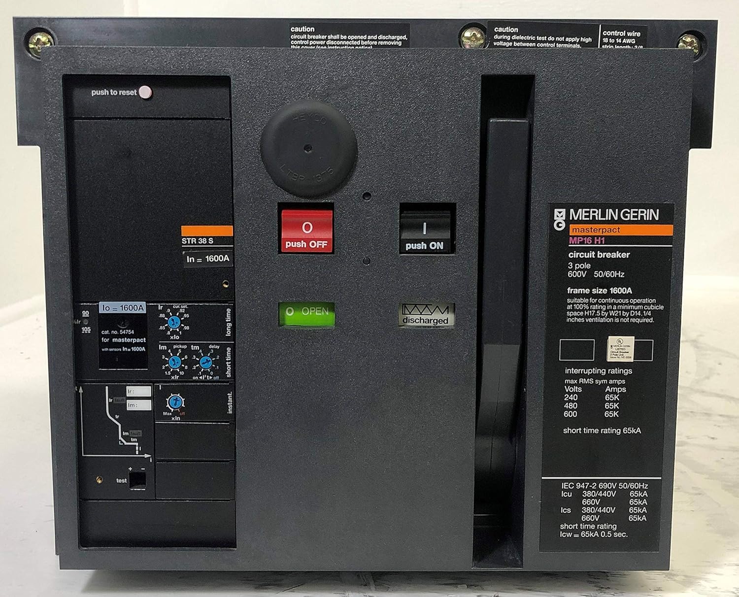
Figure 3.2: Close-up of the front panel, highlighting the "push OFF" and "push ON" buttons, the "O OPEN" and "I CLOSED" indicators, and the STR 38 S trip unit with its various adjustment dials for protection settings.

Figure 3.3: Internal view of the circuit breaker, revealing the mechanical operating mechanism, springs, and linkages responsible for opening and closing the contacts. The "discharged" indicator is visible.

Figure 3.4: Detail of an MX-A Shunt Trip accessory, showing its electrical connections and specifications. This component allows for remote tripping of the circuit breaker.

Figure 3.5: Top view of the circuit breaker, displaying the terminal block for auxiliary contacts and control wiring, along with a diagram indicating various contact configurations and their functions.

Figure 3.6: Bottom view of the circuit breaker, showing the robust copper main power contacts designed to handle 1600 Amps. These contacts are crucial for power connection.
4. Setup and Installation
4.1. Pre-Installation Checks
- Inspect the circuit breaker for any shipping damage.
- Verify that the circuit breaker's ratings (voltage, current, interrupting capacity) match the system requirements.
- Ensure all necessary accessories (e.g., plug-in mounts, auxiliary contacts) are present and correct.
4.2. Mounting
The MP16H1 is designed for plug-in mounting. Ensure the mounting frame or cubicle is securely installed and capable of supporting the weight of the circuit breaker.
- Align the circuit breaker with the plug-in contacts of the mounting frame.
- Carefully slide the circuit breaker into position until it is fully seated and locked.
- Secure any retaining bolts or mechanisms as per the mounting frame's instructions.
4.3. Wiring Connections
Connect the main power cables to the appropriate terminals. Ensure all connections are tight and secure to prevent overheating and arcing.
- Connect the incoming power lines to the upper terminals and the outgoing load lines to the lower terminals.
- Connect any auxiliary control wiring (e.g., for shunt trip, undervoltage release, auxiliary contacts) to the designated terminals as shown in Figure 3.5.
- Verify all wiring against the system's electrical schematics.
5. Operating Instructions
5.1. Charging the Operating Mechanism
Before the circuit breaker can be closed, its operating springs must be charged. This can be done manually or via an optional motor mechanism.
- Manual Charging: Insert the charging handle into the designated slot and pump it until the "charged" indicator is displayed.
- Motor Mechanism: If equipped, the motor mechanism will automatically charge the springs when power is applied or upon a command signal.
5.2. Closing the Circuit Breaker (ON)
Once the springs are charged, the circuit breaker can be closed.
- Ensure the area is clear and all safety precautions are observed.
- Press the green "push ON" button (refer to Figure 3.2). The "I CLOSED" indicator should illuminate.
5.3. Opening the Circuit Breaker (OFF)
To open the circuit breaker, either manually or via a trip event:
- Manual Opening: Press the red "push OFF" button (refer to Figure 3.2). The "O OPEN" indicator should illuminate.
- Automatic Tripping: In case of an overload, short circuit, or ground fault, the trip unit will automatically open the circuit breaker. The trip indicator on the trip unit will show the cause of the trip.
5.4. Resetting After a Trip
After an automatic trip, the circuit breaker must be reset before it can be reclosed.
- Identify and clear the cause of the trip.
- Press the "push to reset" button (refer to Figure 3.2) to reset the trip unit.
- Recharge the operating mechanism (if necessary) and then close the circuit breaker as described in Section 5.2.
6. Maintenance
Regular maintenance is crucial for the long-term reliability and safe operation of the circuit breaker. All maintenance should be performed by qualified personnel with the circuit de-energized and locked out.
6.1. Routine Inspection
- Visually inspect the circuit breaker for any signs of damage, discoloration, or loose connections.
- Check for dust accumulation, especially on ventilation grilles and around terminals.
- Verify that all indicators (ON/OFF, charged/discharged) are functioning correctly.
6.2. Cleaning
- Use a clean, dry, lint-free cloth to wipe down the exterior surfaces.
- For internal cleaning (if required), use a vacuum cleaner with a non-conductive nozzle or compressed air (ensure it is dry and oil-free).
6.3. Functional Testing
Periodically perform functional tests to ensure the trip unit and operating mechanism are working correctly. Refer to the specific test procedures outlined in the detailed technical documentation for the STR 38 S trip unit.
7. Troubleshooting
This section provides guidance on common issues. For complex problems, contact qualified service personnel.
| Problem | Possible Cause | Solution |
|---|---|---|
| Circuit breaker will not close. |
|
|
| Circuit breaker trips immediately after closing. |
|
|
| Indicators not functioning. |
|
|
8. Technical Specifications
| Feature | Detail |
|---|---|
| Brand | Merlin Gerin |
| Model | MP16H1 |
| Current Rating | 1600 Amps |
| Circuit Breaker Type | Standard, LSI Trip Unit (STR 38 S) |
| Mounting Type | Plug-In Mount |
| Number Of Poles | 3 |
| Package Dimensions | 48 x 40 x 20 inches |
| Manufacturer | Merlin Gerin Square D / Schneider Electric |
| Date First Available | March 13, 2014 |
9. Warranty Information
This product is typically covered by a manufacturer's warranty against defects in materials and workmanship. The specific terms and duration of the warranty may vary. Please refer to the original purchase documentation or contact Merlin Gerin / Schneider Electric customer support for detailed warranty information.
Unauthorized modifications or improper installation/operation will void the warranty.
10. Customer Support
For technical assistance, spare parts, or service inquiries, please contact your authorized Merlin Gerin / Schneider Electric distributor or customer support center. When contacting support, please have your product model number (MP16H1) and serial number ready.
You can often find contact information on the manufacturer's official website or through your product supplier.