1. Introduction
The Lazmin TRM01 delay relay module is designed for various control applications requiring timed operations. It features high-quality components, ensuring stable performance and ease of use. This module offers multiple functions, including delay ON, delay OFF, self-locking, and trigger delay, making it versatile for different scenarios.

Figure 1: Top-down view of the Lazmin TRM01 Timer Delay Relay Module, showing the relay, terminals, potentiometer, and function switches.
2. Key Features
- Multiple Functions: Supports delay ON, delay OFF, self-locking, and trigger delay modes.
- Power Protection: Equipped with anti-reverse power protection to prevent damage to the module from incorrect power polarity.
- Voltage Versatility: Available in DC 5V, 12V, and 24V operating voltage versions.
- Adjustable Delay: Delay time can be precisely set between 0.1 seconds and 120 seconds.
- Parameter Retention: All configured settings are automatically saved and retained even after power loss.
3. Specifications
| Feature | Description |
|---|---|
| Working Voltage | DC 5V, 12V, 24V (model specific) |
| Relay Contact Capacity (Normally Closed) | DC 0-28V/10A, AC 0-125V/10A |
| Operating Temperature | -20°C to 60°C (Limit range: -30°C to 70°C) |
| Dimensions (L x W x H) | 60 x 35 x 20 mm (2.36 x 1.38 x 0.79 inches) |
| Adjustable Delay Range | 0.1 seconds to 120 seconds |
| Current Rating | 10 A |
| Mounting Type | DIN Rail Mount |
| Operation Mode | Automatic |
| Coil Voltage (for DC24V model) | 24 Volts (DC) |
| Model Number | Lazmin112sgct06epz5-03 |
| ASIN | B07Y8DCV2S |
| UPC | 719233363027 |
4. Setup and Wiring
Proper wiring is crucial for the safe and correct operation of the module. Refer to the diagram below for terminal identification and connection points.

Figure 2: Detailed view of the module's components, including the input/output terminals, delay adjustment potentiometer, and function selection switches.
4.1. Module Interface
The module features distinct terminals for power input, signal input, and relay output.
Input Voltage/Signal Terminals (3 terminals):
- DC+: Connect to the positive terminal of your DC power supply.
- DC-: Connect to the negative terminal of your DC power supply.
- X1: This is the input signal detection interface. Connect your trigger signal here.
Relay Output Terminals (3 terminals):
- NO (Normally Open): This contact is open when the relay is de-energized and closes when the relay is energized.
- COM (Common): This is the common terminal for the relay switch.
- NC (Normally Closed): This contact is closed when the relay is de-energized and opens when the relay is energized.
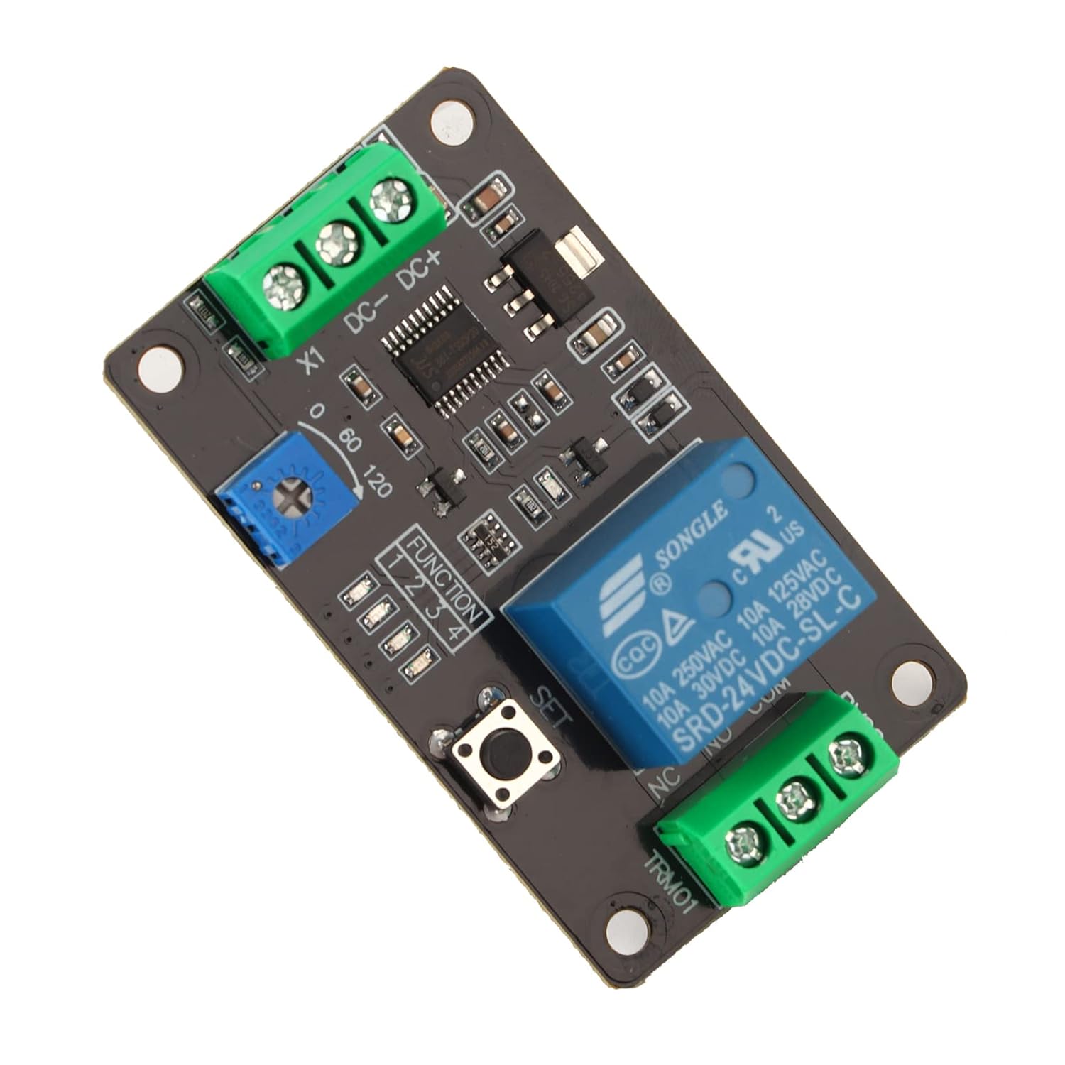
Figure 3: Bottom view of the module, showing solder points and general PCB layout.
5. Operating Instructions
5.1. Setting Delay Time
The delay time is adjusted using the blue potentiometer (trimmer) located on the module. This potentiometer is labeled with a range, typically from 0 to 120, representing seconds. Rotate the potentiometer clockwise to increase the delay time and counter-clockwise to decrease it. The adjustable range is from 0.1 seconds to 120 seconds.

Figure 4: The blue potentiometer used for adjusting the delay time. Rotate to set the desired duration.
5.2. Function Selection
The module supports various operating modes, which are typically selected using DIP switches or a 'SET' button in conjunction with the potentiometer. The specific configuration for each function (Delay ON, Delay OFF, Self-locking, Trigger Delay) will depend on the module's firmware. Refer to the product's detailed function table or specific documentation for exact switch settings if available. Generally, pressing the 'SET' button allows cycling through modes or confirming a setting.
5.3. Saving Settings
The module is designed to automatically save all configured parameters. This means that your chosen delay times and function modes will be retained even if the power supply to the module is interrupted.
6. Maintenance
The Lazmin TRM01 module requires minimal maintenance. Keep the module clean and free from dust and moisture. Periodically inspect wiring connections to ensure they are secure. Avoid exposing the module to extreme temperatures or corrosive environments.
7. Troubleshooting
- Module Not Powering On: Verify that the DC+ and DC- terminals are correctly connected to a power supply within the specified voltage range (5V, 12V, or 24V, depending on your module version) and that the power supply is active. Check for correct polarity.
- Relay Not Activating: Ensure the input signal (X1) is correctly applied according to the selected function mode. Check the delay time setting; if it's too long, the activation might not be immediate.
- Incorrect Delay Time: Adjust the blue potentiometer carefully. Ensure the potentiometer is not damaged or loose.
- Settings Not Retained: The module is designed to save settings automatically. If settings are lost, ensure stable power during configuration and check for any physical damage to the module.
- Intermittent Operation: Check all wiring connections for looseness or corrosion. Ensure the operating environment is within the specified temperature and humidity limits.
8. Safety Information
- Always disconnect power before performing any wiring or maintenance.
- Ensure all connections are secure to prevent short circuits.
- Do not exceed the specified voltage and current ratings for the module and relay contacts.
- Avoid touching live electrical components.
- Install the module in a dry, well-ventilated area, away from flammable materials.
9. Warranty and Support
Specific warranty information and detailed support contacts are not provided within the product details. For warranty claims or technical assistance, please refer to the seller or manufacturer's official website, or contact their customer service directly.