1. Introduction
Thank you for choosing the Wendry DIY Digital Alarm Clock Kit. This kit provides an engaging project for enthusiasts to assemble a multi-functional digital alarm clock featuring time display, temperature measurement, and various animations. This manual will guide you through the assembly process, operation, and maintenance of your new clock.
2. Product Overview and Features
The Wendry DIY Digital Alarm Clock Kit is designed for ease of assembly with a high success rate. Once assembled, it offers several practical features:
- Digital Tube Display: Clear 4-digit LED display for time and temperature.
- Multi-functional: Displays time and temperature alternately.
- Alarm Function: Customizable alarm setting.
- Automatic Brightness: Light control function adjusts display brightness based on ambient light.
- Power-off Memory: Retains settings after power loss.
- Seven Off-line Animations: Includes six time animations for visual interest.
3. Package Contents
Please verify that all components listed below are present in your package before beginning assembly. The kit includes:
- PCB Board (Printed Circuit Board)
- Digital Tube Display Module
- Various Electronic Components (resistors, LEDs, integrated circuits, etc.)
- Installation Accessories (screws, standoffs)
- USB Cable for power supply
- Optional Case Components (may vary by specific kit variant)

Image 3.1: All components of the DIY Digital Alarm Clock Kit, including the PCB, digital display, various electronic parts, and a USB cable, laid out on a flat surface.
4. Assembly Instructions
This kit requires basic soldering skills and careful attention to detail. Ensure you have appropriate tools such as a soldering iron, solder, wire cutters, and a multimeter before starting.
4.1. Component Identification and Preparation
- Unpack all components and compare them with the package contents list.
- Identify each component, paying attention to resistor values, LED polarities (long leg is positive), and integrated circuit orientations (notch or dot indicates pin 1).
4.2. PCB Assembly
- Begin by soldering the smallest components first, such as resistors and diodes, followed by capacitors.
- Install the integrated circuits (ICs) into their respective sockets or solder them directly, ensuring correct orientation.
- Solder the LEDs around the circular perimeter of the PCB, observing correct polarity. The longer lead typically connects to the positive (+) pad.
- Mount the 4-digit digital tube display module onto its designated pads on the PCB.
- Solder any remaining components, such as buttons or sensors, according to the PCB markings.

Image 4.1: The fully assembled Printed Circuit Board (PCB) of the digital alarm clock, showing the central 4-digit display and the surrounding red and blue LEDs.
4.3. Case Assembly (If applicable)
If your kit includes a case, follow these steps:
- Identify the top, bottom, and side panels of the case.
- Carefully remove any protective films from the case panels.
- Assemble the side panels with the bottom panel using the provided screws or interlocking tabs.
- Insert the assembled PCB into the case, aligning it with the mounting holes. Secure it with standoffs and screws if provided.
- Attach the top panel, ensuring all buttons and display elements align correctly with the case openings.

Image 4.2: The unassembled cardboard components that form the protective case for the digital alarm clock kit.
5. Operating Instructions
Once assembled, connect the clock to a 5V USB power source using the provided USB cable.
5.1. Powering On
Connect the USB cable to the clock's power input and a 5V USB power adapter (not included) or a computer USB port. The clock display will illuminate, showing the current time or a default setting.
5.2. Setting Time
Refer to the buttons on the clock (typically labeled 'SET', 'UP', 'DOWN' or similar). Press the 'SET' button to enter time setting mode. Use 'UP'/'DOWN' buttons to adjust hours and minutes. Press 'SET' again to confirm each setting and move to the next. The clock will automatically exit setting mode after a period of inactivity or after cycling through all settings.
5.3. Setting Alarm
To set the alarm, typically press the 'SET' button multiple times until the alarm time display appears (often indicated by an 'AL' prefix or a small alarm icon). Use 'UP'/'DOWN' to set the desired alarm hour and minute. There may be an option to enable/disable the alarm. Confirm settings with 'SET'.
5.4. Temperature Display
The clock is designed to alternate between displaying the time and the current temperature automatically. No manual intervention is usually required for this function.
5.5. Light Control (Automatic Brightness)
The clock features an automatic light control function. A built-in sensor detects ambient light levels and adjusts the display brightness accordingly to improve readability and save power. This feature can typically be toggled on or off through the settings menu, if desired.
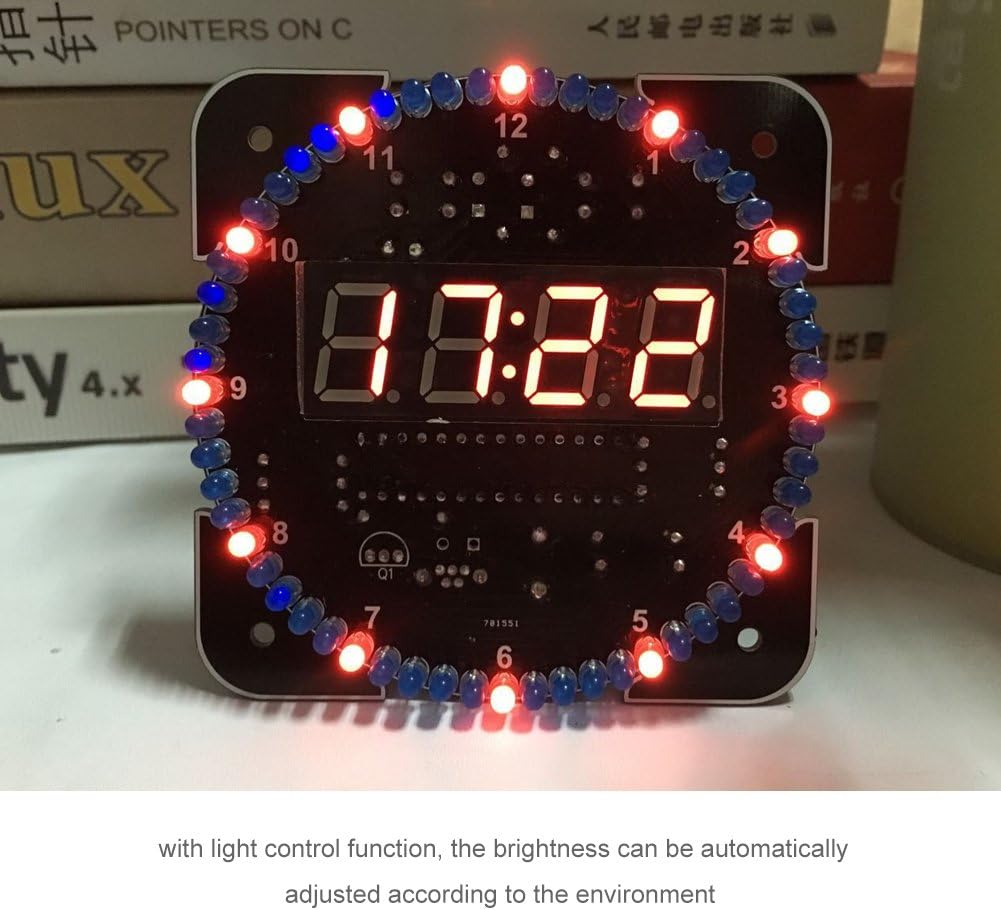
Image 5.1: The assembled digital alarm clock displaying the time '07:22' with its surrounding red and blue LEDs illuminated, demonstrating its operational state.
6. Maintenance
To ensure the longevity and proper functioning of your Wendry Digital Alarm Clock Kit, follow these maintenance guidelines:
- Cleaning: Use a soft, dry cloth to gently wipe the display and case. Avoid abrasive cleaners or solvents.
- Environment: Keep the clock in a dry environment, away from direct sunlight, extreme temperatures, and high humidity.
- Power Supply: Always use a stable 5V USB power source.
7. Troubleshooting
If you encounter issues with your Wendry Digital Alarm Clock Kit, refer to the following common problems and solutions:
- Display Not Lighting Up:
Solution: Check the USB power connection. Ensure the power source is active and providing 5V. Verify all soldered connections on the PCB, especially for the digital display module and main power lines. - Incorrect Time/Temperature Display:
Solution: Re-enter the time setting mode and adjust the time. For temperature, ensure the temperature sensor (if external) is correctly connected and not obstructed. - Alarm Not Sounding:
Solution: Check if the alarm function is enabled in the settings. Ensure the alarm volume (if adjustable) is not set to zero. - LEDs Not Illuminating Correctly:
Solution: Check the polarity of the individual LEDs and their soldered connections. Ensure no short circuits are present. - Buttons Not Responding:
Solution: Verify the button connections on the PCB. Ensure the buttons are not stuck or physically damaged.
8. Specifications
| Brand | Wendry |
| Model Number | Wendrybzvkedx0uf-02 |
| Material | Plastic (for case, if included) |
| PCB Board Size | 81MM X 81MM (3.19 x 3.19 inches) |
| Operating Voltage | 5V (USB powered) |
| Display Type | Digital LED |
| Functions | Time, Temperature, Alarm, Power-off Memory, Light Control, Animations |
| Item Weight | Approximately 4.6 ounces (130g) with USB Cable and Case |

Image 8.1: Diagram illustrating the dimensions of the digital alarm clock's PCB, measuring 3.19 inches in both width and height.
9. Warranty and Support
For warranty information and technical support, please refer to the documentation provided with your purchase or contact the retailer. Keep your proof of purchase for any warranty claims.


