QSC CO-000493-00
QSC CO-000493-00 6-Position Female Euro/Terminal Output Block User Manual
Model: CO-000493-00
Introduction
This manual provides detailed instructions for the installation, operation, and maintenance of the QSC CO-000493-00 6-Position Female Euro/Terminal Output Block. Please read this manual thoroughly before using the product to ensure proper and safe operation.
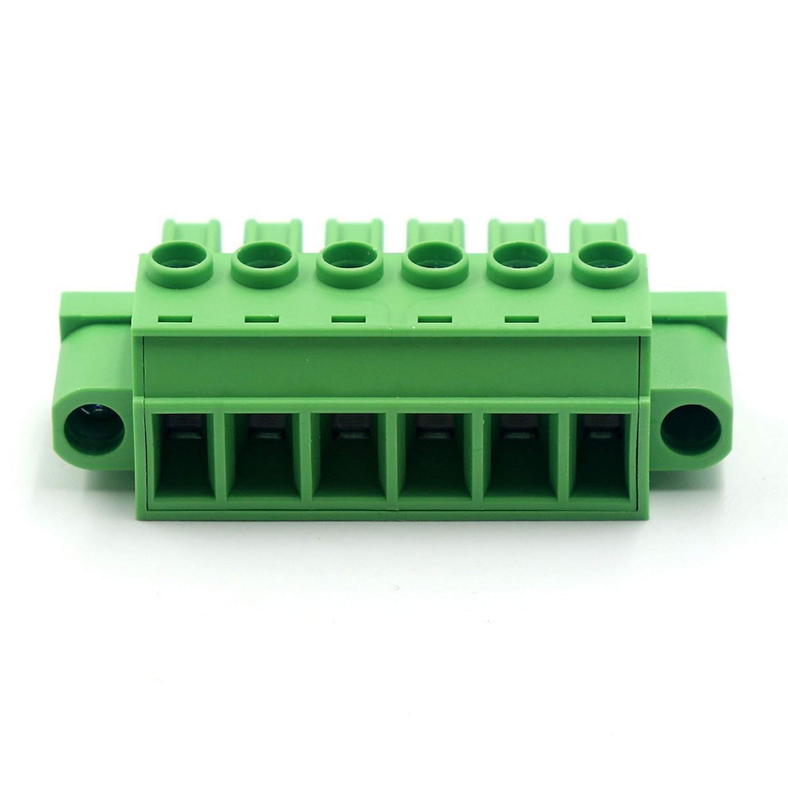
Figure 1: The QSC CO-000493-00 6-Position Female Euro/Terminal Output Block. This image shows the green plastic housing with six female Euro/terminal positions on the front and corresponding connection points on the top.
Safety Information
Always observe the following safety precautions:
- Ensure power is disconnected before installation or maintenance.
- Only qualified personnel should perform electrical connections.
- Do not exceed the specified current and voltage ratings (30 Amps, 12 Volts DC).
- Inspect the block for any damage before use.
Specifications
| Feature | Detail |
|---|---|
| Model Number | CO-000493-00 |
| Connector Type | Plug-In, Female Euro/Terminal Output Block |
| Number of Positions/Poles | 6 |
| Current Rating | 30 Amps |
| Voltage Rating | 12 Volts (DC) |
| Item Pitch | 7.62 Millimeters |
| Mounting Type | PCB Mount |
| Material | Copper |
| Item Weight | 6 Pounds |
Setup and Installation
The QSC CO-000493-00 is designed for PCB mounting. Follow these steps for proper installation:
- Prepare the PCB: Ensure the Printed Circuit Board (PCB) has the correct hole pattern for a 6-position Euro/Terminal block with a 7.62mm pitch.
- Align the Block: Carefully align the pins of the output block with the corresponding holes on the PCB.
- Mount the Block: Gently press the block into place until it sits flush against the PCB surface.
- Solder Connections: Solder the pins of the output block to the PCB pads. Ensure strong, clean solder joints for reliable electrical contact.
- Connect Wires: Insert the stripped ends of the wires into the appropriate terminal positions. Use a small screwdriver to tighten the screw terminals, securing the wires firmly. Ensure no stray wire strands are present that could cause short circuits.
- Verify Connections: Double-check all connections for correct polarity and secure fastening before applying power.
Operating Instructions
Once installed, the QSC CO-000493-00 functions as a reliable interface for electrical connections. Its operation is straightforward:
- Wire Insertion: To connect a wire, loosen the screw terminal for the desired position. Insert the stripped end of the wire into the opening.
- Secure Connection: Tighten the screw terminal until the wire is firmly secured. Do not overtighten, as this can damage the terminal or the wire.
- Wire Removal: To remove a wire, loosen the corresponding screw terminal and gently pull the wire out.
- Mating Plug: This female block is designed to mate with a compatible male plug (not included). Ensure the mating plug has the correct pin configuration and pitch (7.62mm) for proper connection.
Maintenance
The QSC CO-000493-00 is designed for long-term reliability with minimal maintenance. However, periodic checks are recommended:
- Visual Inspection: Periodically inspect the block for any signs of physical damage, discoloration, or loose connections.
- Connection Integrity: Ensure all wire connections remain tight. Vibrations or environmental factors can sometimes loosen screw terminals over time.
- Cleaning: If necessary, gently clean the exterior of the block with a dry, lint-free cloth. Do not use liquid cleaners or solvents.
- Environmental Conditions: Ensure the operating environment remains within suitable temperature and humidity ranges to prevent material degradation.
Troubleshooting
Most issues related to the output block stem from improper installation or connection. Consider the following if you encounter problems:
| Problem | Possible Cause | Solution |
|---|---|---|
| No electrical continuity through a terminal. | Loose wire connection; improperly stripped wire; cold solder joint on PCB. | Tighten screw terminal; re-strip and re-insert wire; re-solder connection to PCB. |
| Intermittent connection. | Partially loose wire; damaged wire insulation near terminal; vibration. | Ensure wire is fully inserted and screw is tight; inspect wire for damage and replace if necessary; consider vibration dampening if applicable. |
| Overheating of the block or wires. | Exceeding current rating; poor connection causing high resistance. | Verify current draw does not exceed 30 Amps; check all connections for tightness and proper soldering. |
If problems persist after following these steps, contact QSC technical support.
Warranty Information
QSC products are manufactured to high quality standards. For specific warranty terms and conditions, please refer to the official QSC website or the warranty card included with your purchase. Keep your proof of purchase for warranty claims.
Customer Support
For technical assistance, product inquiries, or service, please visit the official QSC website or contact their customer support department. You can often find FAQs, drivers, and additional resources online.
QSC Official Website: www.qsc.com
QSC Store on Amazon: Visit the QSC Store
Ask a question about this manual
Ask about setup, troubleshooting, compatibility, parts, safety, or missing instructions. Manuals+ will review the question and use this page’s manual context to help answer it.