1. Introduction
This user manual provides detailed instructions for the safe and efficient operation of the QJE PS3010N Adjustable Digital DC Power Supply. This device is designed to provide a stable and adjustable DC voltage and current output, suitable for various electronic testing, research, and development applications. Please read this manual thoroughly before operating the unit and retain it for future reference.
2. Safety Instructions
WARNING: Failure to follow these safety instructions may result in electric shock, fire, or damage to the power supply or connected equipment.
- Ensure the input voltage matches the power supply's rating (220V AC).
- Do not operate the power supply in wet or damp conditions.
- Do not open the casing of the power supply. There are no user-serviceable parts inside. Refer all servicing to qualified personnel.
- Ensure proper ventilation. Do not block the cooling fan or vents.
- Connect the ground terminal of the power supply to a proper earth ground.
- Before connecting or disconnecting any load, ensure the power supply is turned off or the output is set to zero.
- Avoid short-circuiting the output terminals for extended periods, even though the unit has short-circuit protection.
3. Product Overview
The QJE PS3010N is a compact and efficient digital DC power supply. Familiarize yourself with its components:
3.1 Front Panel
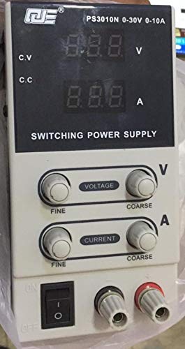
Figure 1: Front Panel Layout of QJE PS3010N
This image displays the front panel of the QJE PS3010N power supply, showing the digital voltage and current displays, voltage and current adjustment knobs (fine and coarse), power switch, and output terminals.
- Digital Voltage Display (V): Shows the output voltage in Volts.
- Digital Current Display (A): Shows the output current in Amperes.
- Voltage Adjustment Knobs (Fine/Coarse): Used to set the desired output voltage. The coarse knob makes large adjustments, while the fine knob allows for precise tuning.
- Current Adjustment Knobs (Fine/Coarse): Used to set the desired current limit. The coarse knob makes large adjustments, while the fine knob allows for precise tuning.
- Power Switch (ON/OFF): Toggles the main power to the unit.
- Output Terminals (+/-): Connect your load here. Red for positive (+), Black for negative (-).
- CV/CC Indicators: LEDs indicating Constant Voltage (CV) or Constant Current (CC) operating mode.
3.2 Rear Panel
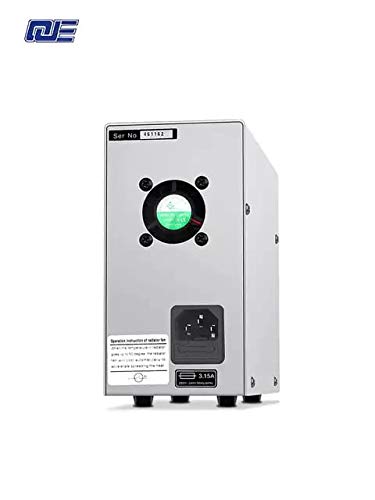
Figure 2: Rear Panel Layout
This image shows the rear panel of the power supply, featuring the AC power input socket, cooling fan, and fuse holder.
- AC Power Input: Connect the provided AC power cord here.
- Cooling Fan: Automatically adjusts speed based on internal temperature to ensure optimal cooling.
- Fuse Holder: Contains the main protective fuse for the unit.
4. Setup
- Unpacking: Carefully remove the power supply from its packaging. Inspect for any signs of damage during transit.
- Placement: Place the unit on a stable, level surface with adequate ventilation. Ensure there is sufficient space around the cooling fan at the rear.
- Power Connection:
- Ensure the power switch on the front panel is in the "OFF" position.
- Connect the provided AC power cord to the AC power input socket on the rear panel.
- Plug the other end of the AC power cord into a grounded 220V AC wall outlet.
- Initial Check: Before connecting any load, turn on the power supply. The digital displays should illuminate, showing default voltage and current readings.
5. Operating Instructions
5.1 Powering On/Off
- To Power On: Flip the power switch on the front panel to the "ON" position. The displays will light up.
- To Power Off: Flip the power switch to the "OFF" position. The displays will turn off.
5.2 Adjusting Voltage
- Ensure no load is connected or the load can safely handle the maximum voltage.
- Use the Coarse Voltage knob to set the voltage close to your desired value.
- Use the Fine Voltage knob to precisely adjust the voltage to the exact required value.
- The voltage display will show the current output voltage.
5.3 Adjusting Current Limit
The current adjustment knobs set the maximum current the power supply will deliver. This is crucial for protecting sensitive circuits.
- Method 1 (Without Load):
- Set the desired output voltage (e.g., 5V).
- Short-circuit the output terminals (connect positive to negative with a short, thick wire for a brief moment). The CC indicator will light up, and the current display will show the maximum current.
- Use the Coarse Current and Fine Current knobs to set the desired current limit.
- Remove the short circuit. The power supply will return to constant voltage mode.
- Method 2 (With Load):
- Connect your load.
- Set the voltage to your desired value.
- Adjust the current limit knobs. If the load draws less than the set limit, the unit operates in CV mode. If the load attempts to draw more than the set limit, the unit switches to CC mode, and the output voltage will drop to maintain the set current.
5.4 Constant Voltage (CV) and Constant Current (CC) Modes
- Constant Voltage (CV) Mode: When the load current is below the preset current limit, the power supply maintains a constant output voltage as set by the voltage knobs. The CV indicator will be lit.
- Constant Current (CC) Mode: When the load current reaches the preset current limit, the power supply automatically switches to constant current mode. The output voltage will decrease to prevent the current from exceeding the set limit. The CC indicator will be lit.
5.5 Protection Functions
The power supply incorporates several protection mechanisms:
- Over-Voltage Protection (OVP): Protects the load from excessive voltage.
- Short Circuit Protection (OCP): Limits current in case of a short circuit at the output.
- Over-Temperature Protection (OTP): Shuts down the unit if internal temperature exceeds safe limits.
6. Maintenance
- Cleaning: Disconnect the power supply from the AC outlet before cleaning. Use a soft, dry cloth to wipe the exterior. Do not use abrasive cleaners or solvents.
- Ventilation: Regularly check that the cooling fan and vents are free from dust and obstructions to ensure proper airflow.
- Fuse Replacement: If the unit does not power on, check the fuse located on the rear panel. Replace it only with a fuse of the same type and rating (e.g., 3.15A).
- Storage: When not in use for extended periods, store the power supply in a cool, dry place, away from direct sunlight and extreme temperatures.
7. Troubleshooting
| Problem | Possible Cause | Solution |
|---|---|---|
| Unit does not power on. | No AC power; Blown fuse; Faulty power cord. | Check AC outlet and power cord connection. Replace fuse if necessary. |
| No output voltage/current. | Output terminals not connected; Voltage/current knobs set to zero; Unit in CC mode with low current limit. | Ensure proper connections. Adjust voltage/current knobs. Check CC indicator and current limit setting. |
| Output voltage drops unexpectedly. | Load current exceeds set current limit (CC mode activated). | Increase the current limit using the current adjustment knobs or reduce the load. |
| Unit overheats and shuts down. | Blocked ventilation; Excessive load; High ambient temperature. | Ensure clear airflow around the fan. Reduce load. Operate in a cooler environment. |
8. Specifications
- Input Voltage: 220V AC
- Output Voltage: 0-30V DC
- Output Current: 0-10A DC
- Output Power: 300W (Max)
- Display Resolution: 100mV / 10mA
- Power Effect: CV ≤ 1% + 10mV
- Load Effect: CV ≤ 1% + 5mV
- Ripple Noise: CV ≤ 200mVp-p
- Indication Accuracy: LCD/V: 1% ± 1d; LCD/A: 1% ± 2d
- Cooling Method: Intelligent temperature control fan, forced air cooling
- Working Environment: -10°C to 40°C, Relative humidity <80%
- Storage Environment: -20°C to 40°C, Relative humidity <80%
- Dimensions: 205mm x 85mm x 160mm (approx.)
- Item Weight: 1.5 kg (approx.)
9. Warranty and Support
This QJE PS3010N power supply comes with a 1 Month Warranty from the date of purchase. This warranty covers manufacturing defects under normal use. It does not cover damage caused by misuse, accident, unauthorized modification, or improper operation.
For technical support or warranty claims, please contact your retailer or the manufacturer, QJE, with your purchase details and model number.
Manufacturer: QJE


