1. Introduction
This manual provides detailed instructions for the installation, operation, and maintenance of the Comimark 2Pcs 12V On-Board Battery Low Voltage Alarm Buzzer Under Voltage Protection Module (Model LY519). This module is designed to monitor the voltage of a 12V battery system, providing an audible alarm and protection against over-discharge or over-charge, thereby extending battery lifespan.
2. Safety Information
- Always disconnect power before installation or maintenance.
- Ensure correct polarity when connecting the module to prevent damage.
- This device is intended for 12V battery systems; do not use with other voltage systems unless specified.
- Keep the module dry and away from conductive materials.
3. Package Contents
- 2 x Comimark 12V On-Board Battery Low Voltage Alarm Buzzer Under Voltage Protection Module (Model LY519)
4. Product Overview
The Comimark LY519 module is a compact circuit board featuring a digital LED display, control buttons, and terminal blocks for connections. It integrates a relay for load control and a buzzer for audible alerts. The module's design allows for precise voltage monitoring and configurable protection thresholds.
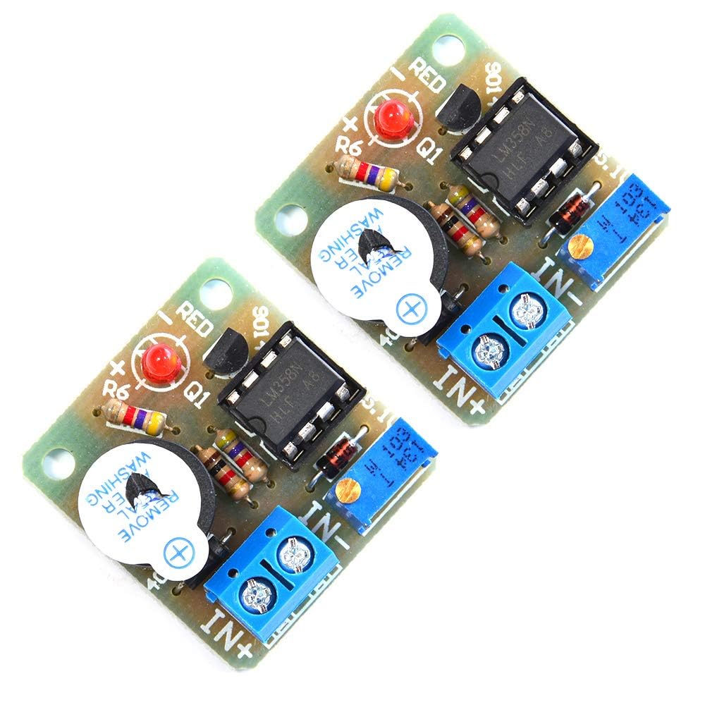
Figure 1: Front view of the Comimark LY519 module, showing the digital display, control buttons, and terminal blocks.

Figure 2: Top-down view of the module, highlighting the main components including the relay and capacitors.

Figure 3: Bottom view of the module, showing the PCB traces and mounting holes.

Figure 4: Close-up of the module's components, including the voltage display and adjustment buttons.
5. Setup and Wiring
Proper wiring is crucial for the correct function and safety of the module. Refer to the diagrams and instructions below for connecting the module to your 12V battery system and load.
5.1. General Wiring
Connect the battery positive (+) to the 'IN+' terminal and battery negative (-) to the 'IN-' terminal. Connect your load (e.g., LED lights, motor) to the 'OUT+' and 'OUT-' terminals. Ensure all connections are secure and observe correct polarity.
Video 1: Demonstration of wiring and initial calibration for a 12V-36V DC Voltage Protection Module. This video illustrates the process of connecting the module and adjusting its settings for accurate voltage monitoring and cutoff.
5.2. Discharge Mode Quick Application
This mode is used to protect batteries from over-discharge by cutting off the load when voltage drops below a set point.
Video 2: Quick start guide for setting up the module in discharge mode (low voltage protection). It demonstrates connecting the battery and load, and configuring the cutoff voltage.
5.3. Charging Mode Quick Application
This mode is used to protect batteries from over-charge by disconnecting the charger when voltage rises above a set point.
Video 3: Quick start guide for setting up the module in charging mode (overcharge protection). It demonstrates connecting the battery and charger, and configuring the cutoff voltage.
6. Operating Instructions
The module offers both low voltage discharge protection and overcharge protection modes, configurable via its onboard buttons and display.
6.1. Calibration
To ensure accurate voltage readings, calibrate the module's display against a known accurate voltmeter. Press and hold the 'SET' button for 3 seconds until the display flashes. Use the 'UP' and 'DOWN' buttons to adjust the displayed voltage to match your reference voltmeter. Press 'SET' again to save.
6.2. Setting Low Voltage Protection (Discharge Mode)
In discharge mode, the module will cut off power to the load when the battery voltage drops below a set threshold. Double-tap the 'SET' button. The display will show 'CL'. Use 'UP' and 'DOWN' to set the desired low voltage cutoff point. Press 'SET' to save. The module will automatically reconnect the load when the voltage rises above a recovery threshold (typically 1V higher than the cutoff, but can be adjusted).
6.3. Setting Overcharge Protection (Charge Mode)
In charge mode, the module will disconnect the charger when the battery voltage reaches a set upper threshold. Double-tap the 'SET' button. The display will show 'CH'. Use 'UP' and 'DOWN' to set the desired overcharge cutoff point. Press 'SET' to save. The module will automatically reconnect the charger when the voltage drops below a recovery threshold (typically 1V lower than the cutoff, but can be adjusted).
6.4. Manual Mode
The module can also be operated in manual mode. If available, switch 'SWITCH 1' to 'M' position. In this mode, you may need to manually press a button (e.g., S1) to start or stop the module, depending on the specific model variant and configuration. Automatic mode is generally recommended for continuous protection.
7. Troubleshooting
- Inaccurate Voltage Display: If the displayed voltage does not match your multimeter, perform the calibration procedure outlined in the 'Calibration' section.
- Alarm Not Activating or Activating Prematurely: Verify the low voltage cutoff and recovery thresholds are set correctly. Recalibrate the module if necessary. Ensure the module is receiving stable power.
- Module Not Powering On: Check all wiring connections for proper polarity and secure contact. Ensure the input voltage is within the module's operating range (8-60V).
- Excessive Battery Drain (Standby Current): While the module is designed for low standby current, ensure no external factors are contributing to drain. If modifications were made (as suggested in some user reviews), revert them or consult an expert.
- Load Not Disconnecting/Reconnecting: Check the relay's functionality. Ensure the load current does not exceed the module's maximum rating (40A).
8. Specifications
| Feature | Value |
|---|---|
| Brand | Comimark |
| Power Source | Battery Powered |
| Color | Red |
| Item Weight | 0.02 Kilograms (0.634 ounces) |
| Min. Operating Voltage | 8 Volts |
| Item Model Number | LY519 |
| UPC | 657835718336 |
| Package Dimensions | 4.69 x 3.03 x 0.59 inches |
9. Maintenance
- Keep the module clean and free from dust and debris.
- Avoid exposure to moisture, extreme temperatures, and corrosive environments.
- Regularly inspect wiring for signs of wear or damage.
10. Warranty and Support
No specific warranty or support information is provided in the product data. For assistance, please refer to the retailer or manufacturer's general support channels.