1. Introduction
This manual provides detailed instructions for the assembly, operation, and maintenance of your YMDK GK64X Wired Hot-Swappable Mechanical Keyboard Kit. The GK64X is a highly customizable 64-key keyboard kit featuring a hot-swappable PCB, allowing for easy switch replacement without soldering. It supports both 3-pin and 5-pin mechanical switches and includes per-switch RGB lighting.
2. What's in the Box
- Plastic Case
- Feet
- Stabilizers
- GK64x Hotswap Type C PCB
- Plate
- USB Cable
- Removal Tool
- Space Module (supports 6.25u space and split double space)
3. Setup and Assembly
Follow these steps to assemble your GK64X keyboard kit. Ensure all components are present before beginning.
3.1 Case and Plate Overview
The kit includes a durable plastic case and a plate. The plate is designed to be screwed directly to the case. The included stabilizers are pre-lubed and sturdy.

Figure 1: Top view of the assembled case and plate, ready for switches.

Figure 2: Angled view showcasing the plate and stabilizer mounts.

Figure 3: Bottom view of the keyboard case.
3.2 PCB Installation
The GK64X features a black, high-quality hot-swappable PCB that supports both 3-pin and 5-pin switches. It includes pre-soldered RGB LEDs under each switch position. Ensure the PCB is correctly aligned within the case before securing.

Figure 4: The GK64X hot-swappable PCB.
3.3 Switch and Keycap Installation
The hot-swappable design allows for easy installation of Cherry MX switches and clones. Optical switches are not supported. Carefully align the switch pins with the PCB sockets and press firmly until seated. If a key is not working after plugging, check for bent switch pins and ensure a 90-degree insertion.
The kit supports a 6.25u spacebar and split double space options. If you wish to use a standard GH60 case, a non-replaceable GH60 size plate would be required.
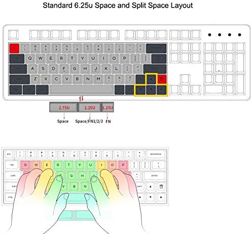
Figure 5: Standard 6.25u Space and Split Space Layout Diagram.
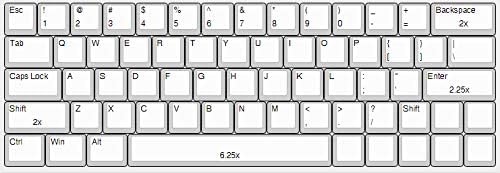
Figure 6: 64-Key Layout Diagram.
After installing all switches, carefully place your desired keycaps onto the switches.
4. Operating Instructions
4.1 Connectivity
The GK64X is a wired keyboard and connects via a USB Type-C cable. A braided cable is included in the kit.
4.2 Programmability and RGB Lighting
The PCB is fully programmable using the GK6x Plus software, which can be downloaded from the official website. The Fn key is located at the right of the bottom row and its position cannot be changed. The keyboard features full 16.8 million RGB backlighting under each switch, supported by a 32-bit MCU chipset with 8M Flash.
5. Maintenance
To ensure the longevity and optimal performance of your keyboard, regular maintenance is recommended:
- Cleaning: Use a soft brush or compressed air to remove dust and debris from between keycaps. For deeper cleaning, keycaps can be removed using the included keycap puller.
- Stabilizers: The included stabilizers are pre-lubed. For linear switches, you may uninstall and clip them for a better tactile feeling. For clicky switches, the current status can be maintained.
6. Troubleshooting
- Keys Not Working: If some keys are not functioning after switch installation, check if the switch pins are bent. Ensure switches are plugged in at a 90-degree angle above the plate.
- Software Issues: If you encounter issues with LEDs or keycodes, refer to the GK6x Plus software documentation or contact customer support.
7. Specifications
| Feature | Detail |
|---|---|
| Model Number | GK64X |
| Connectivity | Wired (USB Type-C) |
| Keyboard Layout | 64-key |
| Switch Compatibility | Cherry MX switches and clones (3-pin, 5-pin), Hot-swappable. Optical switches not supported. |
| Backlighting | Per-switch RGB (16.8 million colors) |
| Case Material | Acrylonitrile Butadiene Styrene (ABS) Plastic |
| Dimensions | 13.39 x 5.51 x 1.97 inches |
| Item Weight | 1.1 pounds |
8. Warranty and Support
For any issues encountered after assembling your kit, including problems with LEDs or keycodes, please contact the seller directly. They will assist you in resolving the issue, and if a resolution cannot be found, a PCB replacement may be offered.