Wendry SK2002L808126
Wendry TCP/IP Network 2-Door Access Control Board User Manual
Model: SK2002L808126
1. Introduction
This manual provides comprehensive instructions for the installation, configuration, and operation of the Wendry TCP/IP Network 2-Door Access Control Board. This device is designed to manage access for two doors, supporting various authentication methods and advanced security features. Please read this manual thoroughly before installation and use to ensure proper functionality and safety.
2. Safety Information
Observe the following safety precautions to prevent damage to the device or injury to personnel:
- Ensure the power supply is disconnected before performing any wiring or maintenance.
- Use only the specified power supply (12VDC; 4-7A).
- Avoid exposing the device to moisture, extreme temperatures, or corrosive environments.
- Installation should be performed by qualified personnel in accordance with local electrical codes.
- Do not attempt to open or repair the device yourself. Refer all servicing to authorized personnel.
3. Package Contents
Verify that all items are present in the package:
- 1 x Wendry TCP/IP Network 2-Door Access Control Board
- 1 x Software CD
- 1 x User Manual (this document)

Image 3.1: The Wendry TCP/IP Network 2-Door Access Control Board and the accompanying software CD. The board features multiple connection terminals and an Ethernet port for network communication.
4. Product Overview
4.1 Key Features
- Flexible User Rights: Supports multi-user supervision and quick settings for user access.
- Remote & Offline Operation: Enables remote unlocking, offline functionality, and real-time supervision.
- Multiple Unlocking Methods: Supports card unlocking, password unlocking, and combined card+password unlocking.
- Advanced Alarm Linkage: Provides alarms for invalid card swiping, long door open times, and illegal break-ins. Supports software interface alarms and hardware alarms with expansion boards.
- High-Speed Memory: Ensures records are not lost during power interruptions.
- Time Attendance Management: Features normal shift and multi-shift time attendance, with exportable and printable reports.
- Anti-Passback & Anti-Tail: Enhanced security features for controlled entry and exit.
4.2 Components
The access control board includes various terminals for power, readers, locks, and sensors. It features an Ethernet port for TCP/IP communication and indicator LEDs for status monitoring.
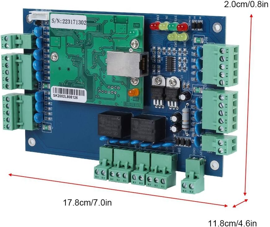
Image 4.1: The physical dimensions of the access control board are approximately 17.8 cm (7.0 in) in length, 11.8 cm (4.6 in) in width, and 2.0 cm (0.8 in) in height.

Image 4.2: The rear side of the access control board, showing mounting points and circuit board traces.
5. Setup
5.1 Hardware Installation
- Mounting: Securely mount the access control board in a protected environment, away from direct sunlight, moisture, and excessive heat.
- Power Connection: Connect a 12VDC, 4-7A power supply to the designated power input terminals on the board. Ensure correct polarity.
- Reader Connection: Connect Wiegand 26/34 bit compatible card readers to the reader input terminals. The board supports up to four readers for two doors (entry/exit for each door).
- Lock Connection: Connect electric locks to the door lock output terminals.
- Exit Button/Door Sensor Connection: Connect exit buttons and door contact sensors to their respective terminals.
- Network Connection: Connect an Ethernet cable from your network switch or router to the TCP/IP port on the control board.
5.2 Software Installation
Insert the provided Software CD into your computer's CD-ROM drive. Follow the on-screen instructions to install the access control management software. The software supports SQL databases.

Image 5.1: The software CD labeled 'ACCESS CONTROLLER' is included for installing the management software.
6. Operating Instructions
6.1 Initial Configuration
- Launch the installed access control management software.
- Discover the control board on the network. Configure its IP address if necessary.
- Add doors and readers to the system within the software interface.
6.2 User Management
Use the software to add new users, assign access cards, and set up passwords. Configure flexible user rights and access schedules for each individual.
6.3 Access Control Methods
- Card Unlocking: Present a registered card to the reader.
- Password Unlocking: Enter the correct password on the keypad.
- Card + Password Unlocking: Requires both a registered card and a correct password for enhanced security.
- Remote Unlocking: Doors can be unlocked remotely via the management software.

Image 6.1: The access control board facilitates remote unlocking, offline operation, and real-time supervision, allowing administrators to manage access from a networked computer.
6.4 Time Attendance Management
The software allows for the configuration of normal shifts and multi-shifts for time attendance tracking. Reports can be generated, exported to Excel, and printed for review.

Image 6.2: The system supports normal and multi-shift time attendance management, with data conveniently viewable and exportable as reports from the software interface.
6.5 Alarm Linkage
The system provides various alarm functions:
- Software Alarm: If no expansion board is connected, the software interface will display an alarm and activate the computer's loudspeaker.
- Hardware Alarm: When connected to an expansion board, the system can trigger physical alarm devices.
- Strengthened Alarm: With a strengthened expansion board, enhanced safety alarms can be configured.

Image 6.3: The system supports fire and alarm linkage. Without an expansion board, alarms are software-based. With an expansion board, hardware alarms are possible, and a strengthened expansion board offers enhanced safety alarms.
7. Maintenance
- Regular Cleaning: Keep the control board and readers free from dust and debris. Use a soft, dry cloth for cleaning.
- Software Updates: Periodically check for software updates from the manufacturer to ensure optimal performance and security.
- Data Backup: Regularly back up your access control database to prevent data loss.
- Power Interruption Protection: The high-speed memory ensures records are retained during power outages. However, a stable power supply is recommended for continuous operation.

Image 7.1: The system incorporates high-speed memory to protect data and ensure records are not lost in the event of a power interruption, symbolized by the battery icon with a cross and a memory card.
8. Troubleshooting
If you encounter issues, refer to the following common problems and solutions:
- No Power: Check power supply connections and ensure the power adapter is functioning correctly.
- Network Connection Failure: Verify Ethernet cable connection, network settings (IP address), and router/switch status.
- Card Reader Not Responding: Check reader wiring, ensure it's a compatible Wiegand 26/34 bit reader, and verify reader configuration in the software.
- Door Not Unlocking: Check lock wiring, power supply to the lock, and ensure the user's access rights are correctly configured.
- Software Issues: Ensure the software is installed correctly, the database is accessible, and the control board is properly connected and recognized.
For persistent issues, contact technical support.
9. Specifications
| Feature | Specification |
|---|---|
| Communication | TCP/IP |
| Software Support Database | SQL |
| Control Capacity | 2 Doors (Entry & Exit by Card & Keypad or Exit by Hit Button) |
| Power Supply | 12VDC; 4-7A |
| Power Consumption (Circuit Board) | Less than 100mA |
| Reader Input Format | Wiegand 26/34 bit (Compatible with HID, EM, etc.) |
| Quantity of Readers Supported | 4 |
| Door Opening Time Extension Setting | 1-600 Seconds (Adjustable) |
| Dimensions (L x W x H) | 17.8 x 11.8 x 1.8 cm (7.0 x 4.6 x 0.7 in) |
| Model Number | SK2002L808126 |
| UPC | 739904217183 |
10. Warranty and Support
For warranty information and technical support, please refer to the documentation provided with your purchase or contact Wendry customer service. Keep your purchase receipt as proof of purchase.