1. Introduction
This manual provides comprehensive instructions for the setup, operation, and maintenance of your VocoPro Digital-Conference-24-Extend Wireless/Wired Conference System. This system is designed for professional conference environments, offering a robust and expandable solution for up to 24 wireless microphones, with further expansion capabilities for wired microphones.
The Digital-Conference-24-Extend operates in the 900 MHz frequency band, utilizing 24-bit digital technology for clear audio transmission and digital encryption for secure communication. Its plug-and-play design ensures ease of installation and use.
2. Safety Information
- Read all instructions before operating the system.
- Keep this manual for future reference.
- Do not expose the system to rain or moisture.
- Ensure proper ventilation around the receiver unit.
- Use only the power adapter supplied by VocoPro.
- Do not attempt to service this product yourself. Refer all servicing to qualified service personnel.
- Dispose of batteries responsibly according to local regulations.
3. Package Contents
Verify that all items listed below are included in your package. If any items are missing or damaged, contact your dealer immediately.

Image: Overview of the VocoPro Digital-Conference-24-Extend system, showing the main receiver unit, 24 wireless microphone bases with gooseneck microphones, and connecting cables.
- 1x Digital-Conference-24-Extend Receiver Unit (comprising multiple 4-channel receivers)
- 24x Wireless Microphone Bases (DigitalQuad-Conference-Extend or V-2 variants)
- 24x Gooseneck Microphones
- Power Adapter(s) for Receiver
- XLR Audio Cables (for receiver outputs and microphone expansion)
- Rackmount Ears (for receiver installation)
- Screwdriver (for assembly/installation)
- User Manual (this document)

Image: Various accessories included with the system, such as rackmount brackets, power supply, and audio cables.
4. Product Overview
4.1 Receiver Unit
The main receiver unit processes signals from up to 24 wireless microphones. It features individual XLR outputs for each channel and a mixed output.

Image: Rear view of a single 4-channel receiver module, showing the 13.5V Power In, Mix Out (XLR), and individual XLR outputs for Channels 1 through 4.
- 13.5V Power In: Connect the supplied power adapter here.
- Mix Out: XLR output for a combined audio signal from all active microphones connected to this receiver module.
- CH 1-4 (XLR): Individual XLR outputs for each wireless microphone channel paired with this receiver module.
- Antenna Ports: Connect the supplied antennas for wireless signal reception.
4.2 Wireless Microphone Base
Each microphone base includes a gooseneck microphone and controls for power and mute, along with indicators for status and battery level.

Image: Top view of a microphone base, highlighting the Power/Mute button and LED indicators (Green for ON, Yellow for MUTE, Flashing Yellow for Low Battery).
- Power/Mute Button: Press to power on/off or mute/unmute the microphone.
- LED Indicators:
- Green: Microphone is ON and active.
- Yellow: Microphone is Muted.
- Flashing Yellow: Low Battery.
- Gooseneck Microphone Port: Connect the gooseneck microphone here.
4.3 Wired Expansion Ports (DigitalQuad-Conference-Extend / V-2)
Certain microphone bases within the system, such as the DigitalQuad-Conference-Extend and V-2 models, offer additional XLR ports for connecting wired microphones, expanding the system's capacity without using additional wireless frequencies.

Image: Rear view of a DigitalQuad-Conference-Extend microphone base, showing "IN" and "OUT" XLR ports for daisy-chaining wired microphones.

Image: Rear view of a DigitalQuad-Conference-V2 microphone base, showing two "IN" XLR ports for connecting two additional wired microphones.
- IN/OUT (DigitalQuad-Conference-Extend): Allows daisy-chaining of multiple wired microphones.
- IN (DigitalQuad-Conference-V2): Provides two dedicated XLR inputs for wired microphones.
5. Setup Instructions
5.1 Receiver Installation
- Placement: Position the receiver unit(s) in a central location, away from large metal objects or other wireless devices that may cause interference.
- Antennas: Screw the supplied antennas securely into the antenna ports on the rear of each receiver module. Adjust them vertically for optimal reception.
- Audio Connections:
- For individual channel control, connect XLR cables from the CH 1-4 outputs of each receiver module to corresponding inputs on your audio mixer or sound system.
- Alternatively, use the Mix Out XLR port on each receiver module for a combined audio signal from its respective 4 channels.
- Power: Connect the supplied power adapter to the 13.5V Power In port on each receiver module, then plug the adapter into a suitable power outlet. Do not power on the receiver yet.
5.2 Microphone Setup
- Gooseneck Attachment: Carefully screw each gooseneck microphone into its corresponding wireless microphone base.
- Battery Installation: Open the battery compartment on the underside of each microphone base and insert the required batteries (typically AA, refer to the base for specific type and polarity).
- Wired Expansion (Optional): If using wired expansion, connect additional wired microphones to the IN ports on the DigitalQuad-Conference-Extend or V-2 bases using XLR cables. For daisy-chaining, connect the OUT port of one base to the IN port of the next.
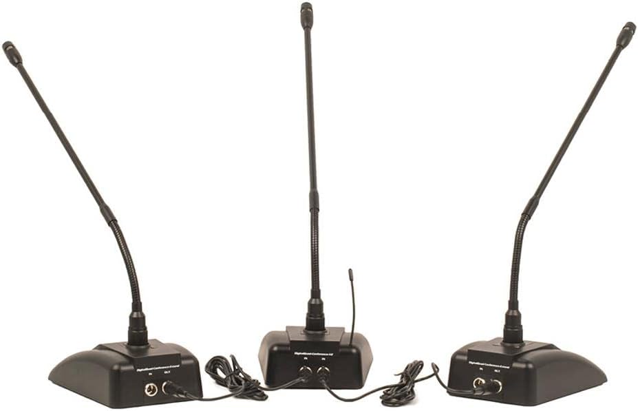
Image: Three microphone bases demonstrating wired expansion. The "OUT" port of one base is connected to the "IN" port of the next, allowing multiple wired microphones to share a single wireless channel.
6. Operating Instructions
- Power On:
- First, power on your audio mixer or sound system.
- Next, power on all VocoPro receiver modules.
- Finally, press and hold the Power/Mute button on each microphone base to power them on. The green LED should illuminate.
- Volume Adjustment: Adjust the individual volume controls on your audio mixer for each microphone channel. The receiver unit itself may also have master volume controls.
- Mute Function: Briefly press the Power/Mute button on a microphone base to mute it. The LED will turn yellow. Press again to unmute (green LED).
- Low Battery Indication: When the battery in a microphone base is low, the LED will flash yellow. Replace batteries promptly to ensure uninterrupted operation.
- Power Off:
- Press and hold the Power/Mute button on each microphone base until the LED turns off.
- Power off all VocoPro receiver modules.
- Finally, power off your audio mixer or sound system.
7. Maintenance
- Cleaning: Use a soft, dry cloth to clean the exterior surfaces of the receiver and microphone bases. Do not use liquid cleaners or solvents.
- Battery Replacement: Regularly check and replace batteries in the microphone bases as needed. Always use fresh, high-quality batteries of the correct type.
- Storage: When not in use for extended periods, store the system in a cool, dry place, and remove batteries from the microphone bases to prevent leakage.
- Cable Inspection: Periodically inspect all cables for signs of wear or damage. Replace any damaged cables immediately.
8. Troubleshooting
| Problem | Possible Cause | Solution |
|---|---|---|
| No sound from microphone. |
|
|
| Intermittent audio or static. |
|
|
| Wired expansion microphones not working. |
|
|
9. Specifications
| Model Name | Digital-Conference-24-Extend |
| Brand | VocoPro |
| Microphone Form Factor | Microphone System |
| Power Source | Corded Electric |
| Signal-to-Noise Ratio | 80 dB |
| Number of Channels | 1 (per receiver module, system supports 24 channels) |
| Frequency Response | 20000 Hz |
| Connectivity Technology | XLR |
| Connector Type | XLR |
| Special Feature | Volume Control |
| Compatible Devices | Audio Mixer |
| Color | Black |
| Polar Pattern | Omnidirectional |
| Item Weight | 55 Pounds (System Total) |
| Package Dimensions | 28 x 23 x 18 inches |
| UPC | 692868243981 |
| Hardware Platform | Television |
10. Warranty and Support
VocoPro products are designed for reliability and performance. For warranty information, technical support, or service inquiries, please refer to the warranty card included with your product or visit the official VocoPro website. Keep your purchase receipt as proof of purchase for warranty claims.
For further assistance, please contact VocoPro customer support directly.