1. Kit Contents and Overview
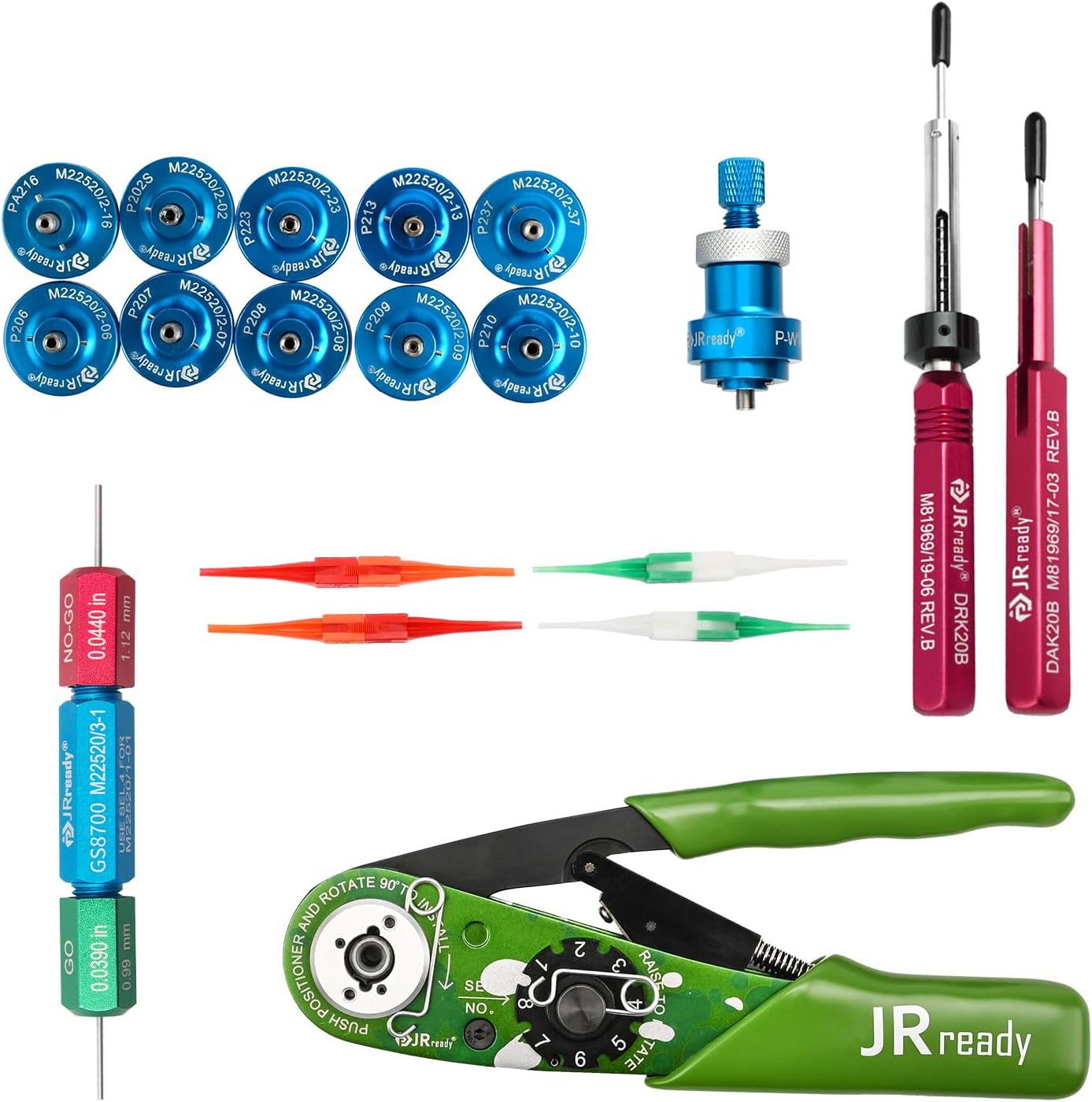
The JRready ST2161-1 Aviation Crimp Tool Kit is designed for precision crimping of solid contacts in MIL-standard, Harting, Wain, and TE connectors. The kit includes the following essential components:

- 4-Indent Crimper (NEW-AS2G, M22520/2-01 Compatible): For crimping wires ranging from 20-32 AWG (0.52-0.032mm²).
- Installing & Removal Tool Set (DAK20B, DRK20B, M81969/14-01, M81969/14-10): Specialized tools for inserting and extracting electrical connector pins.
- G125 GO/NO-GO Gage (M22520/3-01): A precision inspection tool for calibrating and verifying the crimper's accuracy.
- 11-Piece Positioner Kit: Includes P202S (M22520/2-02), P207 (M22520/2-07), P208 (M22520/2-08), P209 (M22520/2-09), P210 (M22520/2-10), P213 (M22520/2-13), PA216 (M22520/2-16), P223 (M22520/2-23), P237 (M22520/2-37), and one Universal Positioner P-W1.
2. The 4-Indent Crimper (NEW-AS2G, M22520/2-01)
2.1. Features
The NEW-AS2G crimper is a 4-indent, 8-impression tool designed for reliable crimps. It features an adjustable selector for various wire sizes.
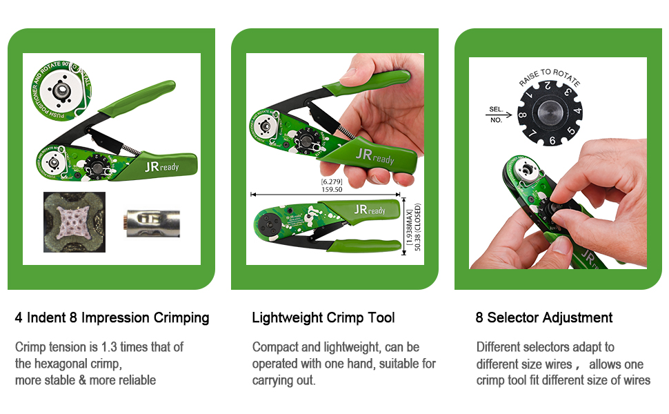
- 4-Indent 8-Impression Crimping: Provides a strong, stable crimp tension.
- Lightweight Design: Compact and operable with one hand for ease of use.
- 8 Selector Adjustment: Allows adaptation to different wire sizes, ensuring precise crimping for various applications.
2.2. How to Use the Crimper
Follow these steps for proper crimping:
- Step 1: Prepare the Crimper. Keep the crimper open. Lift the gearplate and rotate the gear to the desired position corresponding to your wire gauge.
- Step 2: Install the Positioner. Place the appropriate positioner onto the positioning plate. Press down and rotate it 90 degrees to secure it.
- Step 3: Crimp the Wire. Insert the terminal into the crimping hole. Adjust the depth by turning the screw if necessary. Insert the stripped wire into the terminal, then close the crimper handles firmly to complete the crimp.
3. Positioners
3.1. Positioner Kit Overview
The kit includes a variety of positioners designed to ensure accurate contact placement during the crimping process for different connector types.
The 11-piece positioner kit includes:
- P202S (M22520/2-02)
- P207 (M22520/2-07)
- P208 (M22520/2-08)
- P209 (M22520/2-09)
- P210 (M22520/2-10)
- P213 (M22520/2-13)
- PA216 (M22520/2-16)
- P223 (M22520/2-23)
- P237 (M22520/2-37)
- Universal Positioner P-W1
3.2. Installing a Positioner
To install a positioner, align it with the crimper's positioning plate. Push the positioner down and rotate it 90 degrees until it locks securely into place. Ensure it is firmly seated before proceeding with crimping.
4. GO/NO-GO Gage (G125, M22520/3-01)
4.1. Purpose
The G125 GO/NO-GO Gage is a critical tool for verifying the accuracy and calibration of your crimping tool. It ensures that the crimper's indenters meet the required gaging limits for precise and safe crimping.

4.2. Testing Procedure
To test the crimper's calibration using the GO/NO-GO gage:
- Step 1: Close the Tool. Operate the crimping tool to its fully closed position.
- Step 2: Test with 'GO' Gage. Insert the green 'GO' end of the G125 gage into the crimper's indenter opening. If the 'GO' gage passes freely, proceed to the next step. If it does not pass, the tool may require adjustment or service.
- Step 3: Test with 'NO-GO' Gage. Insert the red 'NO-GO' end of the G125 gage into the crimper's indenter opening. The 'NO-GO' gage should not pass completely. If it passes completely, the tool is not qualified and should not be used until serviced.
Only accurate detection with the GO/NO-GO gage ensures the crimper meets the necessary accuracy and safety standards.
5. Installing & Removal Tools
5.1. Tool Identification and Purpose
The kit includes specialized tools for the installation and removal of electrical connector pins, ensuring proper handling without damage.

- DAK20B & DRK20B: These tools are used for 20# pins. The DAK20B is typically for installation, and the DRK20B for removal.
- M81969/14-01 & M81969/14-10: Plastic insertion and removal tools for various electrical connectors.
5.2. Usage with Connectors
These tools are adaptable to various MIL-standard connectors, facilitating the precise handling of contacts.

5.3. Size Specifications for Installation/Removal Tools
The following table provides size specifications for the M81969/14-01 and M81969/14-10 tools:
| Removal Tool P/N | Contact P Number | Wall Thickness of the Installing End | ID of the Installing End | Wall Thickness of the Removal End | ID of the Removal End |
|---|---|---|---|---|---|
| M81969/14-01 | 22D | 0.20 | 1.19 | 0.20 | 1.24 |
| M81969/14-10 | 20 | 0.21 | 1.73 | 0.33 | 1.78 |
6. Maintenance
6.1. General Care
Proper maintenance ensures the longevity and accuracy of your crimp tool kit:
- Cleaning: After each use, wipe down all tools with a clean, dry cloth to remove any debris or residue. For stubborn grime, use a mild, non-abrasive cleaner.
- Lubrication: Periodically apply a light coat of machine oil to the moving parts of the crimper to ensure smooth operation.
- Storage: Store all components in their designated slots within the provided case to prevent damage and loss. Keep the kit in a dry environment to avoid corrosion.
- Inspection: Regularly inspect the crimper's indenters and the GO/NO-GO gage for wear or damage. Replace components as necessary to maintain crimping quality.
7. Troubleshooting
7.1. Common Issues and Solutions
- Issue: Crimps are inconsistent or loose.
Solution: Verify that the correct positioner is installed and that the crimper's selector is set to the appropriate wire gauge. Use the GO/NO-GO gage to check the crimper's calibration. Ensure the wire is properly stripped and inserted into the terminal. - Issue: Difficulty inserting or removing contacts.
Solution: Ensure you are using the correct installation or removal tool for the specific contact size and connector type. Apply gentle, steady pressure. Do not force the tools, as this can damage contacts or connectors. - Issue: Crimper handles are stiff or difficult to operate.
Solution: Clean any debris from the pivot points and apply a small amount of machine oil to lubricate the moving parts. - Issue: Positioner does not seat correctly.
Solution: Check for any obstructions or debris on the positioning plate or the positioner itself. Ensure the positioner is aligned correctly before rotating to lock.
8. Specifications
8.1. Product Specifications
Key specifications for the JRready ST2161-1 Crimp Tool Kit:
| Specification | Value |
|---|---|
| Brand | JRready |
| Model Number | ST2161 |
| Crimper Type | 4-Indent 8-Impression (NEW-AS2G, M22520/2-01 Compatible) |
| Wire Range | 20-32 AWG (0.52-0.032mm²) |
| Gage Type | GO/NO-GO Gage (G125, M22520/3-01) |
| Installation/Removal Tools | DAK20B, DRK20B, M81969/14-01, M81969/14-10 |
| Positioners Included | 11 Pcs (P202S, P207, P208, P209, P210, P213, PA216, P223, P237, P-W1) |
| Item Weight | 0.01 Ounces (for individual component, kit weight varies) |
| Handle Material | Rubber, Thermoplastic Elastomer (TPE) |
| Grip Type | Ergonomic |
9. Warranty and Support
9.1. Contact Information
For warranty information, technical support, or any questions regarding your JRready ST2161-1 Aviation Crimp Tool Kit, please contact JRready customer service directly. Refer to the product packaging or the official JRready website for the most current contact details.
Always ensure you are using genuine JRready replacement parts and accessories to maintain product performance and warranty validity.