1. Introduction
The KOLSOL AT278 is a versatile network cable tester designed for professionals and enthusiasts alike. It integrates multiple functions including cable continuity testing, length measurement, cable scanning, Power over Ethernet (PoE) testing, PING testing, port flash, and Non-Contact Voltage (NCV) detection. This device utilizes advanced Time Domain Reflectometry (TDR) technology for accurate fault location and cable length measurement. Its ergonomic design and rechargeable battery make it suitable for various field applications in network engineering, maintenance, and installation.
2. Product Overview
2.1 Key Features
- Anti-interference Network Cable Testing: Advanced LCD display with intuitive graphical interface for fault location and wiring diagrams. Features TDR technology and AC Interference Rejection.
- Portable & Rechargeable Design: Ergonomic handheld design with a carry case. Built-in 1800mAh 3.7V lithium battery provides approximately 10 hours of operation.
- Multifunctional Capabilities: Integrates Continuity testing, cable scan, port flash, length measurement, POE Power Supply Test, QC testing, and NCV function.
- POE & PING Test: Identifies PoE presence and voltage levels. PING function tests network performance, packets, and response times.
- Length Measurement & Fault Distance: Utilizes TDR theory for accurate cable length measurement and distance to fault information. Displays graphical wire mapping, opens, and shorts.
- Additional Highlights: TF card for data export, integrated voltage detector (90-1000V) in receiver, low voltage alarm, automatic delay power-off, 320*240 LCD color screen, and lighting lamp for dark environments.
2.2 Package Contents
The KOLSOL AT278 package typically includes the following items:
- KOLSOL AT278 Main Tester Unit (Emitter)
- Cable Receiver Unit
- Wiremap Remote Unit
- RJ45 Cable
- RJ11 Cable
- Alligator Clip Cable
- USB Charging Cable
- TF Card
- Carrying Case
- User Manual

Figure 1: Complete KOLSOL AT278 Product Kit
This image displays the complete KOLSOL AT278 kit, including the main tester unit, the cable receiver, the wiremap remote, and various connecting cables and a carrying case.
2.3 Component Identification

Figure 2: KOLSOL AT278 Main Unit and Receiver Components
A detailed view of the KOLSOL AT278 main unit and receiver, highlighting key components such as the LCD screen, function buttons, RJ45/RJ11/BNC ports, TF card slot, probe, and NCV sensor.
Refer to Figure 2 for a visual guide to the main components:
- Main Unit (Emitter): LCD screen, navigation buttons (OK, Up, Down, Left, Right), Power button, Back button, RJ45 MAIN port, RJ11 port, BNC port, RJ45 SCAN port, TF card slot, CHG (charging) port.
- Receiver Unit: Power button, LED light button, SET button, Scanning button, Volume control, Speaker, NCV sensor, Probe, Floodlight, CHG (charging) port.
- Wiremap Remote: RJ45 port.
3. Setup
3.1 Charging the Device
Before first use, fully charge the main unit and receiver. Connect the provided USB charging cable to the CHG port on each unit and to a standard USB power adapter (not included). The charging indicator will show the charging status.
3.2 Powering On/Off
Press and hold the Power button on the main unit or receiver for approximately 3 seconds to turn the device on or off.
3.3 Navigating the Menu
Use the Up/Down/Left/Right navigation buttons to select options on the LCD screen. Press the OK button to confirm a selection. The Back button returns to the previous menu.
4. Operating Instructions
4.1 Cable Continuity Testing (Mapping)
This function checks for short circuits, open circuits, and crossover connections in network cables (RJ45, RJ11) and BNC cables.
- Connect one end of the cable to the appropriate port (RJ45 MAIN, RJ11, or BNC) on the main unit.
- For remote testing, connect the other end of the cable to the Wiremap Remote unit (for RJ45) or the receiver unit (for RJ11/BNC). For local testing, connect both ends to the main unit if applicable.
- From the main menu, select "Mapping" and press OK.
- The LCD will display the wiring diagram, indicating any faults such as opens, shorts, or crossovers.
4.2 Cable Length Measurement
The AT278 uses TDR technology to accurately measure cable length and identify the distance to a fault.
- Ensure the cable is disconnected from all network devices.
- Connect one end of the cable to the RJ45 MAIN, RJ11, or BNC port on the main unit.
- From the main menu, select "Length" and press OK.
- The device will display the measured length of each wire pair and the distance to any detected faults.
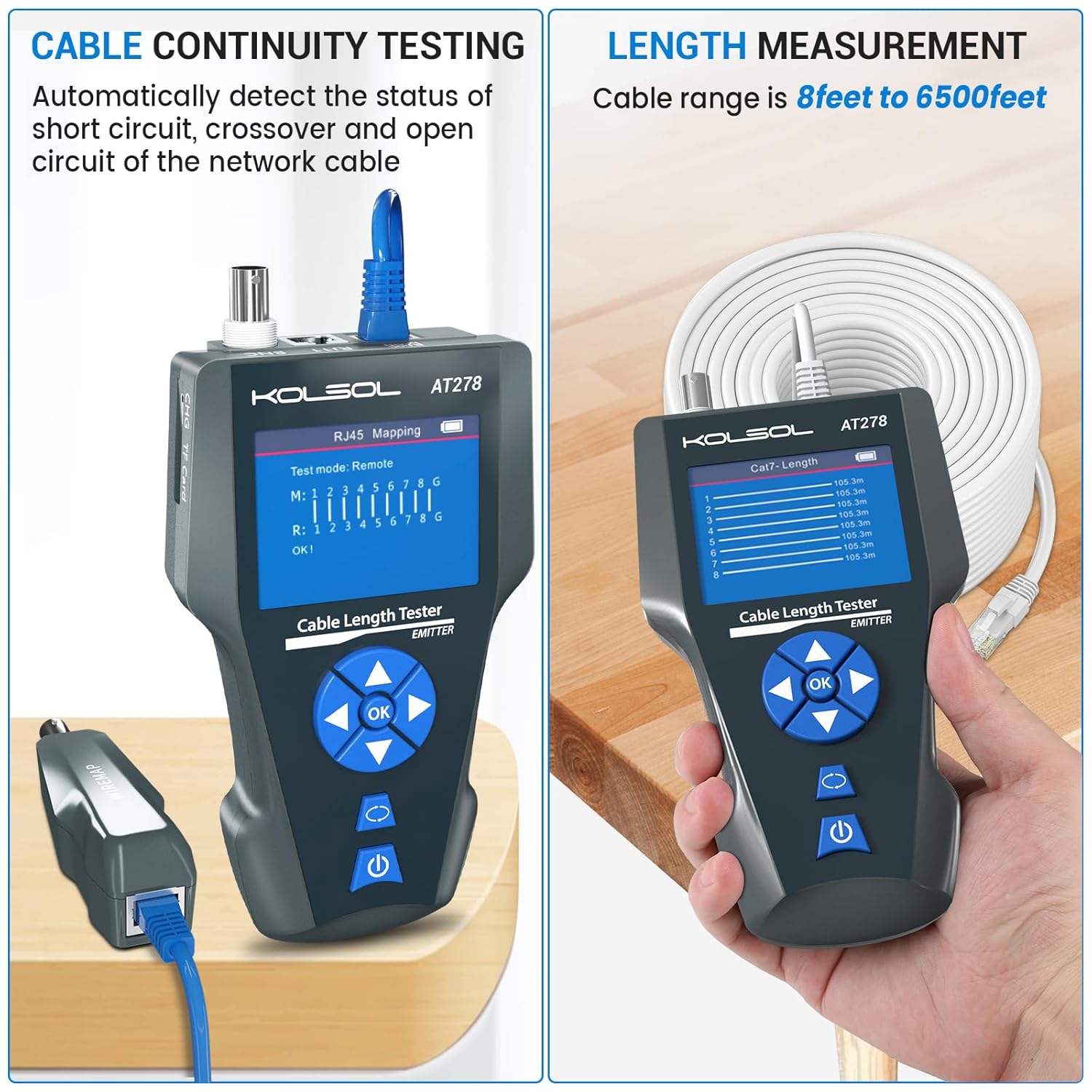
Figure 3: Cable Continuity Testing (Left) and Length Measurement (Right)
The left side shows the AT278 main unit connected for RJ45 cable continuity testing, displaying the wiring diagram. The right side illustrates the device measuring cable length, showing a list of measured segments.
4.3 Cable Scan (Wire Tracking)
This function helps locate a specific cable among a bundle of cables.
- Connect one end of the cable to the RJ45 SCAN port on the main unit.
- From the main menu, select "Scan" and press OK. The main unit will emit a tone.
- Turn on the receiver unit and adjust the volume.
- Move the receiver's probe along the cable bundle. The tone will be loudest when the receiver is near the target cable.
4.4 POE Power Supply Test
This test identifies if Power over Ethernet (PoE) is present on a cable and measures its voltage.
- Connect the network cable from the PoE source to the RJ45 MAIN port on the main unit.
- From the main menu, select "POE" and press OK.
- The display will show the PoE standard, voltage, and power supply mode (e.g., End-span, Mid-span).
4.5 PING Test
The PING test assesses network connectivity and response times.
- Connect the main unit to an active network port using an RJ45 cable.
- From the main menu, select "Ping" and press OK.
- Enter the IP address of the target device (e.g., router, server) using the navigation buttons.
- Press OK to start the PING test. The results will show packet loss, minimum, maximum, and average response times.
4.6 Port Flash
This function helps locate the corresponding port on a network switch or router by making its indicator light flash.
- Connect the main unit to an active network port using an RJ45 cable.
- From the main menu, select "Port Flash" and press OK.
- The main unit will send a signal that causes the connected port's LED on the switch/router to flash, allowing for easy identification.
4.7 NCV (Non-Contact Voltage) Function
The receiver unit includes an NCV sensor to detect AC voltage without direct contact.
- Turn on the receiver unit.
- Move the NCV sensor (tip of the receiver) close to an AC voltage source (e.g., live wire, power outlet).
- If AC voltage is detected, the receiver will emit an audible alarm and/or visual indication.
4.8 Data Transmission (TF Card)
The AT278 allows saving test results to a TF card for later analysis on a computer.
- Ensure a TF card is inserted into the main unit's TF card slot.
- During or after a test, follow the on-screen prompts or menu options to save the data.
- To view data, remove the TF card and insert it into a computer's card reader.

Figure 4: Various Application Scenes of the AT278
This composite image demonstrates various functions: POE testing with a security camera, Port Flash connected to a network switch, data transmission via TF card to a laptop, and PING testing to a network device.
5. Maintenance
- Cleaning: Use a soft, dry cloth to clean the device. Do not use abrasive cleaners or solvents.
- Storage: Store the device in its carrying case in a cool, dry place when not in use. Avoid extreme temperatures and humidity.
- Battery Care: To prolong battery life, avoid fully discharging the battery frequently. Charge the device regularly, even if not in active use, to maintain battery health.
- Firmware Updates: Check the manufacturer's website periodically for any available firmware updates to ensure optimal performance and access to new features.
6. Troubleshooting
- Device Not Powering On: Ensure the battery is sufficiently charged. Connect the device to a power source using the USB charging cable and allow it to charge for at least 30 minutes before attempting to power on again.
- Device Shuts Off Unexpectedly: Check battery level. If the issue persists after a full charge, ensure no power-saving settings are configured to an excessively short duration. Contact support if the problem continues.
- Inaccurate or Inconsistent Test Results:
- Ensure cables are properly terminated and securely connected to the tester ports.
- Verify that the cable type selected in the device settings matches the cable being tested.
- For length measurement, ensure the cable is completely disconnected from all network devices.
- Test with known good cables to calibrate or verify the tester's functionality.
- No Tone During Cable Scan: Ensure the main unit is in "Scan" mode and the receiver is powered on with adequate volume. Check that the cable is properly connected to the RJ45 SCAN port.
- TF Card Not Detected/Data Not Saving: Ensure the TF card is inserted correctly. Try formatting the TF card (this will erase all data) or use a different TF card.
7. Specifications
| Feature | Specification |
|---|---|
| Model Number | AT278 |
| Package Dimensions | 10.83 x 7.99 x 3.62 inches |
| Item Weight | 1.7 Pounds |
| Batteries | 1 Lithium Ion battery required (included) |
| Power Source | Battery Powered |
| Min. Operating Voltage | 3.3 Volts |
| Display | LCD Color Screen (320*240) |
| Voltage Detector (Receiver) | 90-1000V |
| Cable Types Supported | RJ45, RJ11, BNC, Metal Cable |
| Length Measurement Range | 8 feet to 6500 feet (approx. 2.4m to 2000m) |
8. Safety Information
- Do not use the device in wet environments or expose it to water.
- Avoid dropping the device or subjecting it to strong impacts.
- Do not attempt to open or modify the device, as this will void the warranty and may cause damage or injury.
- Use only the specified charging cable and power source.
- When using the NCV function, exercise caution and do not rely solely on the device for determining the presence of live voltage. Always follow proper electrical safety procedures.
- Keep the device out of reach of children.
9. Warranty and Support
KOLSOL products are designed for reliability and performance. For warranty information, technical support, or service inquiries, please refer to the contact information provided with your purchase or visit the official KOLSOL website. Please retain your proof of purchase for warranty claims.