1. Introduction
This manual provides detailed instructions for the installation, operation, and maintenance of your AITRIP AC 110V 10A Automatic Photocell Street Light Switch. This device is designed to automatically control lighting fixtures based on ambient light levels, turning lights on at dusk and off at dawn, thereby enhancing energy efficiency and convenience.
2. Safety Information
WARNING: Risk of Electric Shock.
- Always disconnect power at the circuit breaker or fuse box before installing or servicing this device.
- Installation should be performed by a qualified electrician or in accordance with local electrical codes.
- Ensure all wire connections are secure and properly insulated.
- Do not exceed the specified electrical ratings (110V AC, 10A).
- This device is intended for outdoor use but should be mounted in a manner that protects it from direct water ingress, especially from above.
3. Product Overview
3.1 Features
- Automatic dusk-to-dawn operation.
- Energy-saving design.
- Compact and durable construction.
- Suitable for various outdoor lighting applications.
3.2 Components
The AITRIP Photocell Street Light Switch consists of a light-sensitive sensor, internal switching circuitry, and wire leads for connection. It includes a mounting bracket for secure installation.

Figure 1: AITRIP Photocell Street Light Switches. Each unit features a white sensor housing, a blue base, a metal mounting bracket, and three wire leads (black, white, red).

Figure 2: Detailed view of the photocell switch, highlighting the product label with model number AS-10-110 10A, AC-110/10A, and wire color codes (LOAD RED, NEUT WHITE, LINE BLACK).
4. Specifications
| Parameter | Value |
|---|---|
| Model | AS-10-110 |
| Operating Voltage | AC 110V |
| Current Rating | 10 Amps |
| Operation Mode | Automatic (Dusk to Dawn) |
| Wattage | 1100 watts (Max) |
| Contact Type | Normally Open |
| Connector Type | Wire Leads (Screw Terminal Compatible) |
| Circuit Type | 1-way |
| Contact Material | Brass |
| International Protection Rating | IP54 |
| Dimensions (Approx.) | 40mm x 32mm x 30mm (main body) |

Figure 3: Approximate dimensions of the photocell switch, including the mounting bracket.
5. Setup and Installation
Before beginning installation, ensure all power to the circuit is OFF at the main breaker or fuse box.
5.1 Wiring Instructions
The photocell switch has three color-coded wire leads:
- Black Wire: Connect to the LINE (Live) input from the power source (AC 110V).
- White Wire: Connect to the NEUTRAL wire from the power source and also to the NEUTRAL wire of the lighting fixture.
- Red Wire: Connect to the LOAD (Live) input of the lighting fixture.

Figure 4: Basic wiring diagram. Connect the black wire to the incoming live (input line), the white wire to the neutral (common zero line) and the neutral of the load, and the red wire to the live of the load (output load).

Figure 5: Comprehensive wiring diagram and mounting guidance. The black wire connects to the live source, the white wire connects to the neutral source and the neutral of the lamp, and the red wire connects to the live of the lamp. Ensure the control is installed so it is not directly affected by the light of the turning-ON lamp itself. The diagram also shows correct mounting (sensor facing upwards/outwards) and incorrect mounting (sensor facing downwards or obstructed).
5.2 Mounting Location
Proper mounting is crucial for optimal performance:
- Mount the photocell in a location where it receives natural ambient light throughout the day.
- Avoid mounting it where it will be directly exposed to artificial light sources (e.g., the light it controls, car headlights, streetlights) at night, as this can cause erratic operation (cycling on/off).
- Ensure the sensor is not obstructed by eaves, trees, or other objects that could cast shadows on it during the day or block light at dusk/dawn.
- Mount the unit with the sensor facing upwards or outwards to allow for proper light detection and to prevent water accumulation if possible. Some users recommend mounting sensor down to prevent water ingress, but this can affect light detection. Consider sealing the unit with waterproof silicone if mounting in a position prone to water collection.
6. Operating Instructions
Once properly installed and power is restored, the AITRIP Photocell Street Light Switch operates automatically:
- Dusk: As ambient light levels decrease at dusk, the photocell sensor will detect the change and activate the connected lighting fixture.
- Dawn: As ambient light levels increase at dawn, the photocell sensor will detect the change and deactivate the connected lighting fixture.
- There may be a slight delay (a few seconds to a minute) in switching to prevent false triggers from transient light changes (e.g., car headlights).
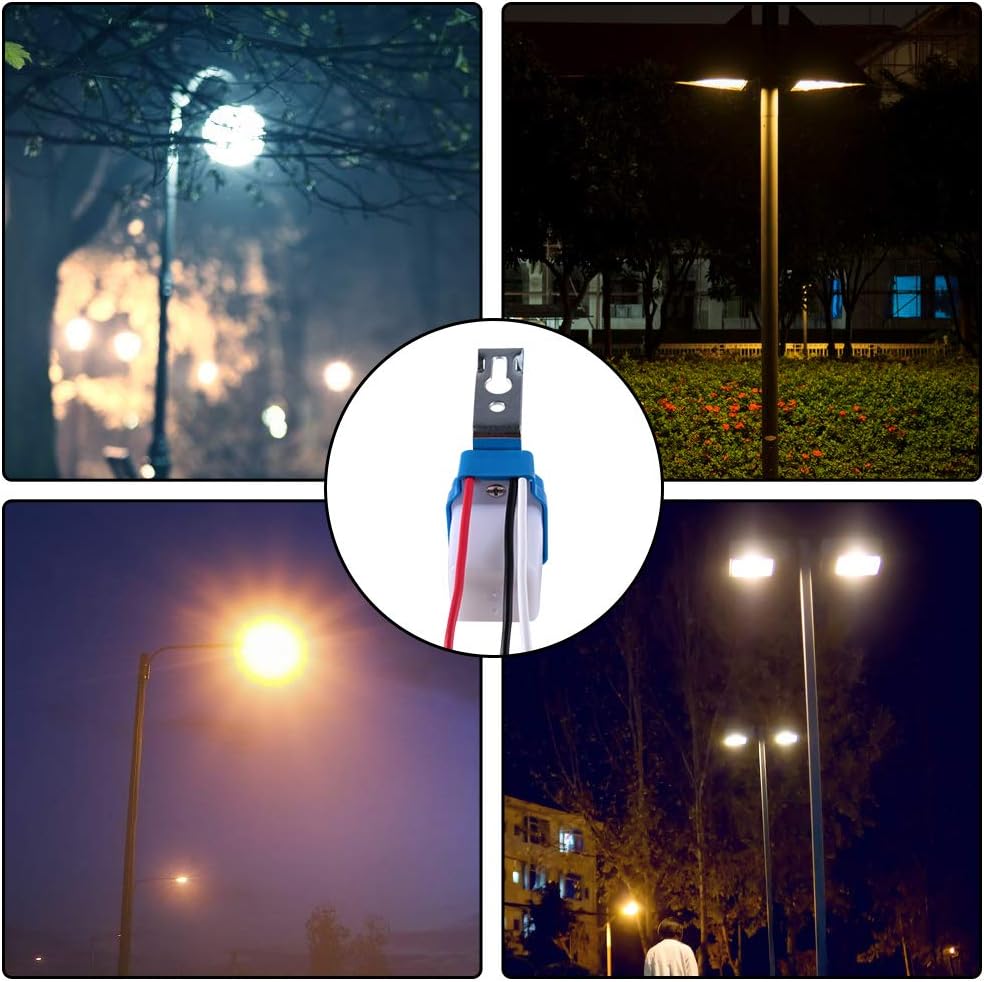
Figure 6: Examples of the photocell switch in use, controlling outdoor lighting fixtures.
7. Maintenance
The AITRIP Photocell Street Light Switch requires minimal maintenance:
- Cleaning: Periodically inspect the sensor window for dirt, dust, or debris. Gently clean with a soft, damp cloth if necessary. Do not use abrasive cleaners.
- Inspection: Annually check wire connections for tightness and signs of corrosion. Ensure the mounting bracket is secure.
- Obstructions: Ensure no new obstructions (e.g., growing foliage) are blocking the sensor's view of ambient light.
8. Troubleshooting
| Problem | Possible Cause | Solution |
|---|---|---|
| Lights stay on during the day. |
|
|
| Lights do not turn on at night. |
|
|
| Lights cycle on/off rapidly. |
|
|
| Water ingress inside the unit. |
|
|
9. Warranty and Support
AITRIP products are designed for reliability and performance. For specific warranty information, please refer to the product packaging or contact your retailer. If you encounter any issues or require technical assistance, please contact AITRIP customer support through your purchase platform or the official AITRIP website.
Please have your model number (AS-10-110) and purchase date available when contacting support.