1. Introduction
This manual provides detailed instructions for the installation, operation, and maintenance of the DEVMO 5 Axis CNC Interface Adapter Breakout Board. This board is designed to facilitate communication between a computer running CNC control software like Mach3 or Linux CNC (EMC2) and stepper motor drivers, enabling precise control of up to five axes in a CNC machine.
The board features opto-isolation for enhanced computer security and a robust design for reliable performance in various CNC applications.

Figure 1: Top view of the DEVMO 5 Axis CNC Interface Adapter Breakout Board. This image shows the main components including the DB25 parallel port connector, USB power input, and terminal blocks for motor driver connections.
2. Product Features
The DEVMO 5 Axis CNC Interface Adapter Breakout Board offers the following key features:
- High Performance: Designed for efficient and reliable operation in CNC systems.
- 5-Axis Support: Capable of controlling up to five independent stepper motor drivers.
- Software Compatibility: Fully compatible with popular parallel-control CNC software such as Mach3 and Linux CNC (EMC2).
- Enhanced Computer Security: USB power supply and peripheral power phases are separated to protect the connected computer.
- Opto-Isolation: All signal lines are opto-isolated, providing electrical isolation and further protecting the computer from electrical noise and surges.
3. Setup Instructions
Follow these steps to properly set up your DEVMO 5 Axis CNC Interface Adapter Breakout Board:
- Power Supply Connection: Connect a 5V DC power supply to the board's USB port. This powers the logic circuits of the breakout board. Ensure the power supply is stable and within the specified voltage range.
- Parallel Port Connection: Connect the DB25 parallel port of the breakout board to the parallel port of your computer using a standard DB25 parallel cable. Ensure the connection is secure.
- Stepper Motor Driver Connections: Connect your stepper motor drivers to the corresponding terminal blocks on the breakout board. The board supports up to 5 axes. Refer to the pinout diagram (if available with your product) for specific connections for Step, Direction, and Enable signals for each axis.
- Limit Switch and E-Stop Connections: If using limit switches, home switches, or an emergency stop button, connect them to the designated input terminals on the breakout board. These inputs are typically opto-isolated for safety.
- Spindle Control (Optional): If your CNC machine includes spindle control, connect the spindle control signals (e.g., PWM, relay control) to the appropriate output terminals on the board.
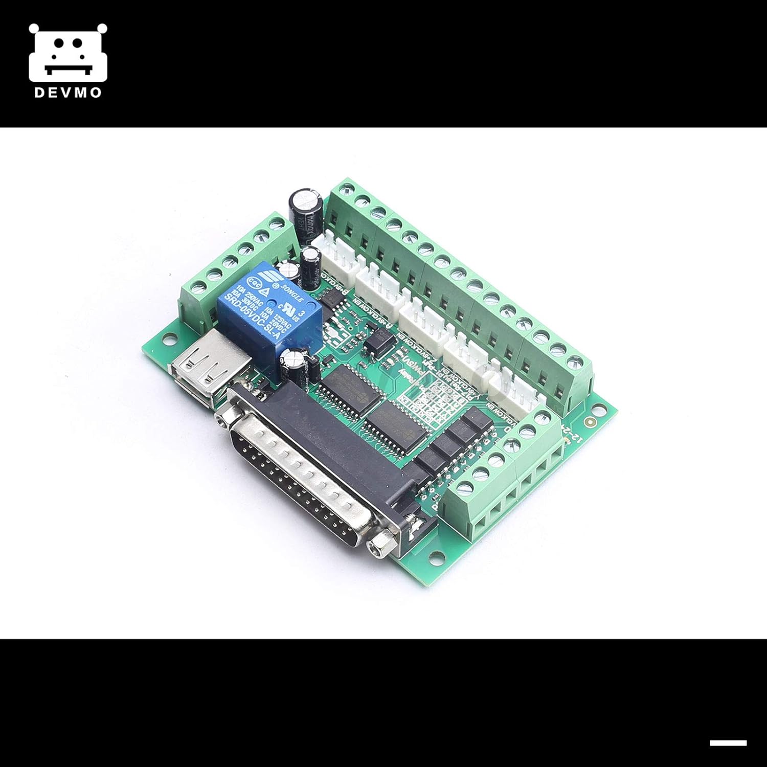
Figure 2: Front view of the breakout board, highlighting the various terminal blocks for connecting stepper motor drivers and other peripherals.

Figure 3: Example of the USB cable and DB25 parallel cable used for connecting the breakout board to a computer and power source.
4. Operating Instructions
Once the hardware setup is complete, configure your CNC control software:
- Install CNC Software: Install Mach3 or Linux CNC (EMC2) on your computer. Ensure your operating system is compatible with the chosen software.
- Configure Parallel Port: In your CNC software settings, configure the parallel port (LPT port) address. This is crucial for the software to communicate with the breakout board.
- Pin Assignments: Assign the correct pin numbers for each axis (Step, Direction, Enable), limit switches, home switches, E-stop, and spindle control outputs within the software. Refer to the breakout board's pinout documentation for accurate assignments.
- Motor Tuning: Perform motor tuning for each axis in the CNC software. This involves setting steps per unit, velocity, and acceleration to match your stepper motors and mechanical system.
- Test Connections: Before running any G-code, perform manual jog tests for each axis to verify that the motors respond correctly to commands. Test limit switches and the E-stop function.
- Load G-code: Load your desired G-code file into the CNC software.
- Start Operation: Initiate the CNC program. Monitor the machine's operation closely, especially during the first run of a new program.
Note: Always ensure all safety precautions are in place before operating any CNC machinery.
5. Maintenance
To ensure the longevity and reliable performance of your DEVMO breakout board, follow these maintenance guidelines:
- Keep Clean: Regularly inspect the board for dust and debris. Use a soft brush or compressed air to gently clean the surface.
- Check Connections: Periodically verify that all terminal block connections and the DB25 parallel port connection are secure. Loose connections can lead to intermittent operation or signal loss.
- Environmental Conditions: Operate the board within its specified environmental conditions (temperature, humidity) to prevent damage. Avoid exposure to excessive moisture or extreme temperatures.
- Cable Integrity: Inspect all connecting cables (USB, parallel, motor driver cables) for signs of wear or damage. Replace any damaged cables immediately.
6. Troubleshooting
If you encounter issues with your DEVMO breakout board, consider the following troubleshooting steps:
- No Power Indicator:
- Ensure the USB cable is securely connected to both the board and a functional USB power source.
- Verify the USB power source is providing 5V DC.
- Motors Not Moving:
- Check all stepper motor driver connections to the breakout board.
- Verify that the motor drivers are powered and enabled.
- Confirm pin assignments in your CNC software match the board's documentation.
- Ensure the parallel port address in the software is correct.
- Check for any E-stop or limit switch activations that might be preventing motion.
- Erratic Motor Movement:
- Review motor tuning settings (steps per unit, velocity, acceleration) in your CNC software.
- Check for electrical noise or interference. Ensure proper grounding.
- Inspect motor wiring for loose connections or shorts.
- Communication Errors:
- Ensure the parallel port cable is fully seated and not damaged.
- Verify that the parallel port is enabled in your computer's BIOS settings.
- Confirm that no other software is conflicting with the parallel port.
7. Specifications
The following are the technical specifications for the DEVMO 5 Axis CNC Interface Adapter Breakout Board:
| Feature | Specification |
|---|---|
| Brand | DEVMO |
| Maximum Supply Voltage | 24 Volts (for peripherals, logic is 5V via USB) |
| Mounting Type | PCB Mount |
| Number of Pins (DB25) | 25 |
| Interface Type | USB (for power), Parallel Port (for data) |
| Axis Support | Up to 5 axes |
| Isolation | Opto-isolated signals |
| Software Compatibility | Mach3, Linux CNC (EMC2) |

Figure 4: Bottom view of the breakout board, showing the PCB traces and components.
8. Warranty and Support
For warranty information and technical support, please refer to the documentation provided with your purchase or contact DEVMO customer service directly. Keep your proof of purchase for warranty claims.
For additional resources and community support related to Mach3 or Linux CNC, please visit their respective official websites or user forums.