1. Product Overview
The DONGKER Voltage to Current Module is designed to convert a 0-5V voltage input signal into a 4-20mA current output signal. This non-isolated module operates with a DC 7-30V power supply and is suitable for various industrial control applications requiring signal conversion.
Key Features:
- Input Voltage: 0-5V
- Output Current: 4-20mA
- Power Supply: DC 7-30V
- High precision resistor (1‰) for stable performance.
- Compact design with dimensions of 40mm x 25mm x 12mm.
2. Setup and Wiring
Proper wiring is crucial for the correct operation of the module. Refer to the diagrams below for connection details.
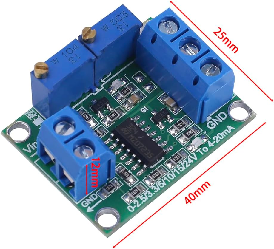
Figure 2.1: Top view of the DONGKER Voltage to Current Module showing dimensions (40mm x 25mm x 12mm) and terminal blocks.

Figure 2.2: Front and back views of the module, illustrating component placement and solder points.
Wiring Connections:
The module features two terminal blocks for connections:
- Input Side (2-pin terminal):
- Vin: Connect your 0-5V input voltage signal here.
- GND: Connect the ground of your input voltage signal here.
- Output/Power Side (3-pin terminal):
- GND: Connect the common ground for the power supply and current loop.
- Iout: This is the 4-20mA current output. Connect this to your receiving device.
- VCC: Connect the DC 7-30V power supply here. The current loop power and module power share this ground.
Important Note: This module is non-isolated. Ensure that the input and output circuits share a common ground or are otherwise compatible to prevent damage or incorrect readings.
Initial Calibration:
The module may require calibration to match specific input voltage ranges or to fine-tune the 4-20mA output. There are two potentiometers (pots) on the module:
- Zeroing Pot: Located near the VCC pin. Adjust this pot to set the 4mA output when the input voltage is 0V.
- Range Pot: Located near the Vin pin. Adjust this pot to set the 20mA output when the input voltage is 5V.
Use a multimeter to accurately measure the output current during calibration. Apply 0V to the input and adjust the zeroing pot until the output is 4mA. Then, apply 5V to the input and adjust the range pot until the output is 20mA. Repeat these steps as necessary for fine-tuning.
3. Operating Instructions
Once properly wired and calibrated, the module will convert the analog voltage input to a proportional current output. Ensure your input voltage source is stable and within the 0-5V range for accurate 4-20mA conversion.
- Apply a DC power supply between 7V and 30V to the VCC and GND terminals on the 3-pin block.
- Apply your 0-5V signal to the Vin and GND terminals on the 2-pin block.
- The module will output a corresponding 4-20mA current signal on the Iout terminal.
For example, a 0V input will result in a 4mA output, and a 5V input will result in a 20mA output, assuming proper calibration.
4. Maintenance
The DONGKER Voltage to Current Module is designed for reliable operation with minimal maintenance. Follow these guidelines to ensure longevity:
- Environmental Conditions: Operate the module within the specified ambient temperature range of -10℃ to 60℃. Store it between -20℃ to 85℃. Maintain relative humidity between 10-90% RH and air pressure between 86-106Kpa.
- Cleaning: Keep the module free from dust and debris. If cleaning is necessary, use a soft, dry cloth. Avoid using liquids or abrasive cleaners.
- Inspection: Periodically inspect wiring connections to ensure they are secure and free from corrosion.
- Modifications: For specific applications, such as battery/solar powered devices, the onboard LEDs may be desoldered to reduce current consumption. This modification should only be performed by experienced users.
5. Troubleshooting
If you encounter issues with your module, consider the following troubleshooting steps:
- Incorrect Output Current:
- Verify the input voltage is stable and within the 0-5V range.
- Re-check calibration using the zeroing and range potentiometers.
- Ensure the power supply is within the DC 7-30V range and stable.
- No Output or Erratic Output:
- Confirm all wiring connections are correct and secure.
- Check for proper power supply to the module.
- Ensure the input signal is a discrete voltage and not high impedance when off, as this can cause the module to output over 45mA. The input must be driven to ground for zero and to max input voltage for span.
- Compatibility Issues:
- Remember the module is non-isolated. Ensure your system design accounts for shared grounds between input and output circuits.
- If using a microcontroller DAC, ensure it can provide sufficient current to drive the module's input, as the input impedance can be low. An op-amp buffer may be required.
6. Specifications
| Parameter | Value |
|---|---|
| Model Number | ae15225a-db7c-4533-ab27-7c15f0a335d6 |
| Power Supply Voltage | DC 7-30V |
| Input Voltage Range | 0-5V |
| Output Current Range | 4-20mA |
| Resistor Precision | 1‰ |
| Temperature Drifting | +/-100ppm/℃ |
| Ambient Operating Temperature | -10℃ ~ 60℃ |
| Storage Temperature | -20℃ ~ 85℃ |
| Relative Humidity | 10-90% RH |
| Air Pressure | 86-106Kpa |
| Dimensions (L x W x H) | 40mm x 25mm x 12mm (approx. 1.57 x 0.98 x 0.47 inches) |
| Item Weight | 0.704 ounces (approx. 20g) |
7. Support
For any questions or technical assistance regarding your DONGKER Voltage to Current Module, please contact the seller or manufacturer directly. Provide your product model number (ae15225a-db7c-4533-ab27-7c15f0a335d6) for efficient support.
The manufacturer, DONGKER, is committed to providing high-quality products and customer satisfaction.