1. Introduction
The PEAKMETER PM2128 is a versatile digital AC/DC clamp meter designed for measuring AC/DC voltage, AC/DC current, resistance, capacitance, frequency, and temperature. It features non-contact voltage (NCV) detection, True RMS measurement, data hold, backlight, flashlight, and an auto power-off function, making it suitable for various electrical testing applications.

Figure 1.1: The PEAKMETER PM2128 Digital AC/DC Clamp Meter with included test leads.
2. Safety Information
Please read and understand all safety information before operating this device. Failure to follow these instructions may result in electric shock, fire, or damage to the meter.
- Always adhere to local and national safety codes.
- Do not use the meter if it appears damaged or if the insulation on the test leads is compromised.
- Ensure the rotary switch is in the correct position for the desired measurement before connecting the test leads.
- Do not measure voltages exceeding the maximum rated input (CAT.III 1000V).
- Exercise extreme caution when working with live circuits.
- Replace batteries promptly when the low battery indicator appears to ensure accurate readings.
- Do not operate the meter in explosive gas, vapor, or dusty environments.
3. Product Overview
Familiarize yourself with the components of your PM2128 clamp meter.
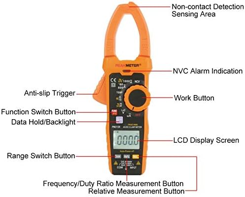
Figure 3.1: Front panel components of the PM2128 clamp meter.
- Clamp Jaw: Used for non-contact AC/DC current measurement.
- Non-Contact Detection Sensing Area: Detects AC voltage without direct contact.
- Rotary Switch: Selects measurement functions (Voltage, Current, Resistance, Capacitance, Frequency, Temperature, NCV, OFF).
- LCD Display: Shows measurement readings, units, and indicators.
- Function (FUNC) Button: Toggles between different measurement modes within a rotary switch setting (e.g., AC/DC voltage, AC/DC current).
- Data Hold/Backlight Button: Short press to hold data, long press to activate/deactivate backlight.
- Range (RAN) Button: Toggles between auto-ranging and manual ranging.
- Hz/% Button: Selects frequency or duty cycle measurement.
- Relative (REL) Button: Activates relative measurement mode.
- Input Jacks (COM, INPUT): Connect test leads for voltage, resistance, capacitance, frequency, and temperature measurements.
- Anti-slip Trigger: Opens and closes the clamp jaw.
4. Setup
4.1 Battery Installation
The PM2128 requires three 1.5V AAA batteries (not included). To install:
- Ensure the meter is turned OFF.
- Locate the battery compartment cover on the back of the meter.
- Use a screwdriver to open the battery compartment.
- Insert three AAA batteries, observing correct polarity (+/-).
- Replace the battery compartment cover and secure it with the screw.
4.2 Connecting Test Leads
For most measurements (voltage, resistance, capacitance, frequency, temperature), connect the test leads as follows:
- Insert the red test lead into the 'INPUT' jack.
- Insert the black test lead into the 'COM' (common) jack.
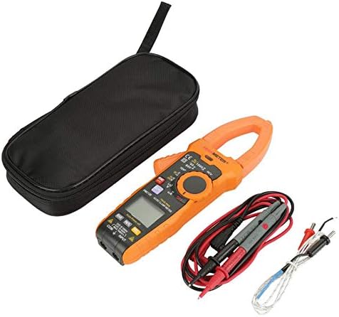
Figure 4.1: The PM2128 meter with its accessories, including test leads and a temperature probe.
5. Operating Instructions
5.1 Power On/Off
Turn the rotary switch from 'OFF' to any measurement function to power on the meter. Turn it back to 'OFF' to power off. The meter features an auto power-off function after approximately 10 minutes of inactivity to conserve battery life.
5.2 AC/DC Voltage Measurement
- Set the rotary switch to the 'V' position.
- Press the 'FUNC' button to toggle between ACV (~) and DCV (—).
- Connect the test leads in parallel to the circuit or component under test.
- Read the voltage value on the LCD.
5.3 AC/DC Current Measurement (Clamp Function)
- Set the rotary switch to the 'A' position.
- Press the 'FUNC' button to toggle between ACA (~) and DCA (—).
- Press the anti-slip trigger to open the clamp jaw.
- Enclose only one conductor of the circuit within the clamp jaw. Ensure the jaw is fully closed.
- Read the current value on the LCD.
5.4 Resistance Measurement
- Set the rotary switch to the 'Ω' position.
- Ensure the circuit or component is de-energized before connecting the test leads.
- Connect the test leads across the component to measure its resistance.
- Read the resistance value on the LCD.
5.5 Capacitance Measurement
- Set the rotary switch to the 'Ω' position, then press 'FUNC' until 'nF' or 'µF' is displayed.
- Ensure the capacitor is fully discharged before connecting the test leads.
- Connect the test leads across the capacitor terminals.
- Read the capacitance value on the LCD.
5.6 Frequency Measurement
- Set the rotary switch to the 'Hz' position.
- Connect the test leads in parallel to the circuit where frequency is to be measured.
- Read the frequency value on the LCD.
5.7 Temperature Measurement
- Set the rotary switch to the 'TEMP' position.
- Connect the temperature probe to the input jacks (ensure correct polarity if applicable).
- Place the probe tip on or near the object whose temperature is to be measured.
- Read the temperature value on the LCD.
5.8 Continuity Test
- Set the rotary switch to the 'Ω' position, then press 'FUNC' until the continuity symbol (a speaker icon) is displayed.
- Ensure the circuit is de-energized.
- Connect the test leads across the component or circuit path.
- An audible beep indicates continuity (resistance less than approximately 30 Ω).
5.9 Non-Contact Voltage (NCV) Detection
- Set the rotary switch to the 'NCV' position.
- Move the meter's NCV sensing area close to the conductor or outlet.
- The meter will emit an audible beep and the NCV alarm indication will light up if AC voltage is detected.
5.10 Data Hold, Backlight, and Flashlight
- Data Hold: Press the 'HOLD' button briefly to freeze the current reading on the display. Press again to release.
- Backlight: Press and hold the 'HOLD' button for approximately 2 seconds to turn the display backlight on or off.
- Flashlight: The flashlight function is typically activated by a dedicated button or a long press of a specific function button (refer to the meter's markings for exact operation).
6. Maintenance
6.1 Cleaning
Wipe the meter's case with a damp cloth and mild detergent. Do not use abrasives or solvents. Ensure the meter is dry before use.
6.2 Battery Replacement
When the low battery indicator appears on the LCD, replace the batteries as described in Section 4.1. Remove batteries if the meter will not be used for an extended period.
6.3 Storage
Store the meter in a cool, dry place, away from direct sunlight and extreme temperatures. If storing for a long time, remove the batteries.
7. Troubleshooting
- No Display: Check battery installation and ensure batteries are not depleted.
- Incorrect Readings: Verify the rotary switch is set to the correct function and range. Ensure test leads are properly connected and making good contact. Check battery level.
- Meter Does Not Respond: Turn the meter off and then on again. If the issue persists, replace batteries.
8. Specifications
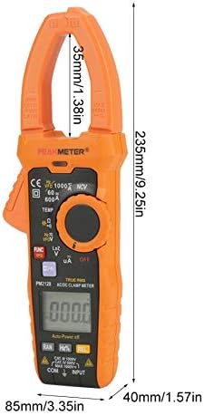
Figure 8.1: Physical dimensions of the PM2128 clamp meter.
| Parameter | Range | Accuracy |
|---|---|---|
| DC Voltage | 6V/60V/600V/1000V | (0.5%+5) |
| AC Voltage (45~1000Hz) | 6V/60V/600V/1000V | (0.8%+5) |
| AC Voltage (45~65Hz) | 6V/60V/600V | (0.8%+5) |
| DC Current | 60A/600A/1000A | (2.5%+8) |
| AC Current (40~65Hz) | 60A/600A/1000A | (3.0%+10) |
| Resistance | 6KΩ/60KΩ/600KΩ/6MΩ/60MΩ | (0.8%+3) |
| Continuity | <30Ω | Audible beep |
| Frequency | 60Hz/1000Hz | (1.0%+5) |
| Temperature | -20℃-1000℃/-4℉-1832℉ | (1.0%+2) |
| Capacitance | 60nF-60mF | (4.0%+3) |
| Low resistance voltage measurement DCV | 1000V | (1.0%+10) |
| Low resistance voltage measurement ACV | 1000V | (2.0%+20) |
| AC µA | 200µA | (0.8%+3) |
General Characteristics
- Display: 6000 Counts
- Voltage Measuring Frequency: 1kHz
- Clamp Measuring Frequency: 1kHz
- Flashlight: Yes
- Backlight: Yes
- Data Hold: Yes
- Non-contact Voltage Detection (NCV): Yes
- Continuity Test: Yes
- Auto Power Off: 10 minutes
- Auto/Manual Measurement: Yes
- Relative Value Measurement: Yes
- True RMS: Yes
- DC µA Measurement: Yes
- Inverter Measurement (VFD): Yes
- Analog Bar: Yes
- Lowpass Filtering: Yes
- Automatic Identification of Current, Voltage and Resistance: Yes
- Battery: 3 x 1.5V AAA Batteries (NOT included)
- Item Size: 235x85x40mm (9.25x3.35x1.57in)
- Clamp Width: 35mm (1.38in)
- Weight: Approx. 596g
- Safety Rating: EN61010-1, EN61010-2-032, EN61326, CAT.III 1000V
- Operating Temperature: 18℃ to 28℃
9. Warranty and Support
For warranty information and technical support, please refer to the documentation provided with your purchase or contact the seller directly. Specific warranty terms may vary by region and retailer.