1. Introduction
This manual provides detailed instructions for the proper use, setup, and operation of the Reland Sun X9C104 Digital Potentiometer Module. The X9C104 is a digitally controlled variable resistor designed for applications requiring precise resistance adjustment, such as in bridge balance circuits, programmable gain amplifiers, and filter tuning.
2. Product Overview
The X9C104 module integrates the X9C104 digital potentiometer IC onto a small printed circuit board (PCB), making it easy to interface with microcontrollers and other electronic systems. It offers 100 tap points, allowing for fine-grained resistance control.
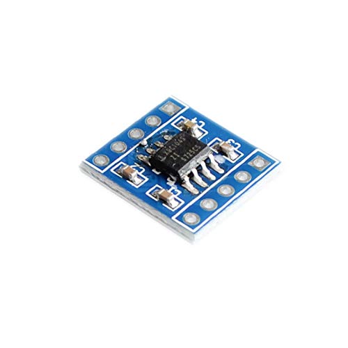
Figure 1: This image shows the top view of the Reland Sun X9C104 Digital Potentiometer Module. The central component is the X9C104 integrated circuit, an 8-pin SOIC package, mounted on a small blue PCB. Surrounding the chip are several small surface-mount capacitors and resistors. The module features through-hole pins along its edges for easy integration into breadboards or custom circuits. The pins are not labeled on this side.
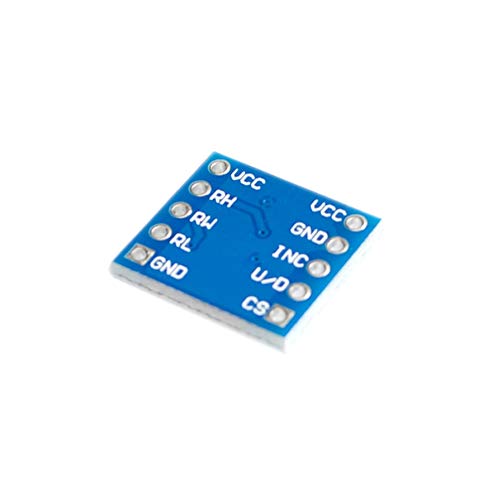
Figure 2: This image displays the bottom view of the Reland Sun X9C104 Digital Potentiometer Module. The blue PCB clearly shows the labels for each of the module's pins: VCC, RH, RL, GND, CS, U/D, and INC. These labels are crucial for correct wiring and operation of the digital potentiometer. The solder points for the X9C104 chip are visible on this side.
Pin Description:
- VCC: Power supply input (typically 5V).
- GND: Ground connection.
- RH: High terminal of the potentiometer.
- RL: Low terminal of the potentiometer.
- RW (Wiper): Wiper terminal of the potentiometer (connected internally to the X9C104 IC).
- CS (Chip Select): Active low input. Enables communication with the module.
- U/D (Up/Down): Direction control input. High for incrementing wiper position, Low for decrementing.
- INC (Increment): Clock input. Each pulse moves the wiper one step in the direction specified by U/D.
3. Specifications
| Operating Voltage | 5V |
| Total Resistance | 100K ohm |
| Port Voltage | -5V to 5V |
| Taps (Wiper Positions) | 100 |
| Interface | CS, U/D, INC |
| Resistance Increase Mode | Linear |
| Working Current | 3mA |
| Package/Temperature Range | 8SOIC / -40°C to 85°C |
4. Setup
To integrate the X9C104 module into your circuit, follow these steps:
- Power Connection: Connect the VCC pin to a 5V power supply and the GND pin to the circuit's ground. Ensure stable power delivery.
- Potentiometer Connections: Connect the RH and RL pins to the points in your circuit where the potentiometer's end terminals are required. The wiper (RW) output is typically used as the variable resistance point.
- Control Signal Connections: Connect the CS, U/D, and INC pins to digital output pins of your microcontroller (e.g., Arduino, ESP32).
- Initial State: It is recommended to initialize the digital potentiometer to a known state (e.g., mid-scale or minimum resistance) upon power-up through your microcontroller's code.
5. Operating Instructions
The X9C104 digital potentiometer is controlled via a three-wire serial interface: CS, U/D, and INC. The wiper position is stored in non-volatile memory, meaning it retains its last setting even after power-off.
Control Sequence:
- Enable Chip: Pull the CS (Chip Select) pin LOW to enable communication with the X9C104 module.
- Set Direction: Set the U/D (Up/Down) pin to HIGH to increment the wiper position (increase resistance from RL to RW) or LOW to decrement the wiper position (decrease resistance from RL to RW).
- Move Wiper: Pulse the INC (Increment) pin. Each rising edge on INC will move the wiper one step in the direction specified by U/D. The X9C104 has 100 tap points, so 100 pulses will move the wiper from one end to the other.
- Latch Position: After the desired number of pulses, pull the CS pin HIGH. This latches the new wiper position into the non-volatile memory. The wiper position will remain at this setting until a new sequence is initiated.
Note: The wiper position can be moved a maximum of 99 steps in either direction from its current position while CS is low. To move more than 99 steps, CS must be brought high and then low again to initiate a new sequence.
6. Maintenance
The Reland Sun X9C104 Digital Potentiometer Module is a robust electronic component. To ensure its longevity and reliable operation:
- Keep the module clean and dry. Avoid exposure to moisture, dust, and corrosive substances.
- Handle with care to prevent physical damage to the PCB or components.
- Avoid static discharge. Use appropriate ESD precautions when handling the module.
- Ensure power supply voltage does not exceed the specified operating voltage of 5V.
7. Troubleshooting
If you encounter issues with your X9C104 module, consider the following:
- No Wiper Movement:
- Verify that the VCC and GND connections are correct and stable (5V).
- Ensure the CS pin is pulled LOW during the control sequence.
- Check that the INC pin is receiving proper pulses and the U/D pin is set correctly.
- Confirm that the CS pin is pulled HIGH after the pulses to latch the new position.
- Incorrect Resistance Value:
- Double-check your control logic for the number of INC pulses and the U/D setting.
- Ensure the RH, RL, and RW connections are correctly integrated into your circuit.
- Measure the resistance directly with a multimeter to confirm the module's output.
- Module Not Responding:
- Inspect for any visible damage to the module or solder joints.
- Test with a different microcontroller or power supply to rule out external issues.
8. Warranty and Support
This product is manufactured by Reland Sun. For technical support, warranty claims, or further assistance, please contact your retailer or the manufacturer directly. Please refer to your purchase documentation for specific warranty terms and contact information.