UEi Test Instruments IRT803
UEi IRT803 Insulation Resistance Tester User Manual
Model: IRT803 | Brand: UEi Test Instruments
1. Introduction
This manual provides essential information for the safe and effective operation of the UEi IRT803 Digital Insulation Resistance Tester. The IRT803 is a versatile instrument designed for measuring insulation resistance, AC/DC voltage, and continuity. It features a 1000V AC/DC measurement capability, auto-ranging, a backlit display, and a DMM rotary style selector. Key functions include Lock, Compare, and Polarization Index (PI)/Dielectric Absorption Ratio (DAR) tests. Please read this manual thoroughly before use to ensure proper handling and to maximize the instrument's performance.
2. Safety Information
Always adhere to safety precautions when using electrical testing equipment. The IRT803 is designed with safety in mind, featuring a CATIV rating up to 600V and CATII up to 1000V, ensuring protection in various jobsite environments. Failure to follow safety instructions can result in electric shock, fire, or damage to the instrument.
- Do not use the tester if it appears damaged or if the test leads are compromised.
- Ensure the correct function and range are selected before making any measurements.
- Always disconnect power to the circuit under test before connecting or disconnecting test leads for resistance measurements.
- Wear appropriate personal protective equipment (PPE), such as insulated gloves and safety glasses.
- Do not operate the tester in wet conditions or in the presence of explosive gases or dust.
- Replace batteries promptly when the low battery indicator appears to ensure accurate readings.
3. What's in the Box
Upon unpacking, verify that all items listed below are present and undamaged:
- UEi IRT803 Insulation Resistance Tester
- Silicone test leads with alligator clips (red and black) (ATL57)
- Insulation test probe with alligator clips (red & black)
- 4 AA Batteries
- User Manual
- Soft carrying case

Image 3.1: All components included with the UEi IRT803 Insulation Resistance Tester, including the meter, test leads, probes, batteries, manual, and soft carrying case.
4. Product Overview
The IRT803 is designed for ease of use and durability. It features an easy-to-read LCD display with a backlight for visibility in various lighting conditions, and a work light to illuminate dark environments. The unit is protected by a rugged rubber boot, which also includes convenient test lead holders for compact storage. An auto power-off function helps conserve battery life.
4.1. Key Features and Functions
- 600V AC/DC Measurement: Capable of measuring both alternating and direct current voltages up to 600V.
- Insulation Resistance: Measures resistance from 0.01MΩ up to 2GΩ with test voltages of 50V, 100V, 250V, 500V, and 1000V.
- Continuity: For checking circuit continuity.
- Compare Reading Function: Allows for comparison against a set reference value.
- PI/DAR Test: Automatic calculation of Polarization Index and Dielectric Absorption Ratio for advanced insulation diagnostics.
- A-Hold/Hold: Freezes the displayed reading for convenient recording.
- Lock Reading: Locks the test voltage for continuous insulation testing.
- Rotary Dial Selector: Intuitive selection of measurement functions and test voltages.
- Protective Rubber Boot: Enhances durability and provides lead storage.

Image 4.1: Front view of the IRT803 showing the LCD display, rotary selector, and function buttons.

Image 4.2: Visual representation highlighting the main functions and features of the IRT803.
5. Setup
5.1. Battery Installation
The IRT803 requires four (4) AA batteries for operation. To install or replace batteries:
- Ensure the tester is powered off.
- Locate the battery compartment on the rear of the unit.
- Use a screwdriver to open the battery compartment cover.
- Insert the four AA batteries, observing the correct polarity (+/-) as indicated inside the compartment.
- Securely close the battery compartment cover.
5.2. Connecting Test Leads
Connect the test leads to the appropriate input jacks on the tester. For most measurements, the red lead connects to the 'V Ω INSULATION' jack and the black lead connects to the 'COM' (common) jack. Ensure connections are firm and secure.

Image 5.1: The IRT803 with test leads properly connected to the input jacks.
6. Operating Instructions
6.1. Powering On/Off and Display Backlight
- To power on the unit, rotate the selector dial from 'OFF' to any desired measurement function.
- To power off, rotate the selector dial back to 'OFF'. The unit also features auto power-off to save battery life after a period of inactivity.
- Press the SELECT button (often indicated by a light bulb icon) to toggle the display backlight on or off.
6.2. Insulation Resistance Testing
The IRT803 can perform insulation resistance tests at various voltages.
- Select Test Voltage: Rotate the selector dial to the desired insulation test voltage (50V, 100V, 250V, 500V, or 1000V).
- Connect Test Leads: Connect the red test lead to the circuit under test and the black test lead to the ground or common point. Ensure the circuit is de-energized.
- Initiate Test: Press and hold the large red TEST button to begin the insulation test. The test voltage will be applied, and the resistance reading will be displayed.
- Lock Function: For continuous testing, press the LOCK button after initiating the test. This will maintain the test voltage without needing to hold the TEST button. Press TEST again to unlock.
- Compare Function: Use the COMPARE button to set a reference value and compare subsequent readings against it.
- PI/DAR Test: Select the PI/DAR function on the dial. The meter will automatically perform the Polarization Index and Dielectric Absorption Ratio tests, displaying the calculated values.
- Read and Record: Observe the reading on the LCD. Use the HOLD button to freeze the display for easier recording.
- Discharge: After completing an insulation test, the circuit under test should be discharged. The IRT803 typically handles this automatically, but always exercise caution.

Image 6.1: The IRT803 being used to measure insulation resistance on electrical wiring.

Image 6.2: A close-up view of the test leads securely connected to the IRT803's input terminals.
6.3. Voltage Testing (AC/DC)
To measure AC or DC voltage up to 600V:
- Rotate the selector dial to the 'V' position.
- Connect the red test lead to the positive or live point and the black test lead to the negative or neutral/ground point of the circuit.
- The display will show the measured voltage. The meter will automatically detect AC or DC voltage.
6.4. Continuity Testing
To check for continuity in a circuit:
- Rotate the selector dial to the 'Ω' (Ohms) position, which typically includes continuity.
- Connect the test leads across the component or circuit path you wish to test.
- If there is continuity (low resistance), the meter will typically emit an audible beep and display a low resistance value.
7. Maintenance
7.1. Cleaning
To maintain the accuracy and longevity of your IRT803:
- Wipe the casing with a damp cloth and mild detergent. Do not use abrasives or solvents.
- Ensure the unit is completely dry before storage or next use.
7.2. Battery Replacement
Replace batteries as described in Section 5.1 when the low battery indicator appears on the display. Always use fresh AA alkaline batteries.
7.3. Storage
When not in use, store the IRT803 in its soft carrying case in a cool, dry environment, away from direct sunlight and extreme temperatures. If storing for extended periods, remove the batteries to prevent leakage.
8. Troubleshooting
If you encounter issues with your IRT803, refer to the following common problems and solutions:
| Problem | Possible Cause | Solution |
|---|---|---|
| Tester does not power on | Dead or incorrectly installed batteries | Check battery polarity; replace with fresh AA batteries. |
| No reading on display | Incorrect function selected; open circuit; poor test lead connection | Verify selector dial position; ensure test leads are firmly connected to the circuit and the meter; check for breaks in the circuit. |
| Inaccurate readings | Low battery; environmental interference; incorrect range/function | Replace batteries; move away from strong electromagnetic fields; ensure correct function and test voltage are selected. |
| Test leads not working | Damaged leads; poor connection | Inspect leads for damage; ensure they are fully inserted into the jacks. Replace if damaged. |
If the problem persists after attempting these solutions, please contact UEi Test Instruments customer support.
9. Specifications
| Parameter | Value |
|---|---|
| Model Number | IRT803 |
| Brand | UEi Test Instruments |
| Insulation Test Voltages | 50V, 100V, 250V, 500V, 1000V |
| Insulation Resistance Range | 0.01MΩ to 2GΩ |
| Insulation Resistance Accuracy | ±1.5-3% + 5 digits (0.01MΩ-500MΩ) |
| Voltage Measurement | Up to 600V AC/DC |
| Continuity Range | 20.00 Ω to 20.0 kΩ (as per product description) |
| Safety Rating | CATIV 600V, CATII 1000V |
| Power Source | 4 x AA Batteries |
| Display | LCD with Backlight |
| Product Dimensions | 2.7 x 3.52 x 8.27 inches |
| Item Weight | 1.8 Pounds |
| Color | Yellow |
10. Warranty Information
The UEi IRT803 Insulation Resistance Tester is backed by a 1-year limited warranty from the date of purchase. This warranty covers defects in materials and workmanship under normal use. It does not cover damage resulting from misuse, unauthorized modification, accident, or neglect. For specific terms and conditions, please refer to the warranty card included with your product or contact UEi Test Instruments customer support.
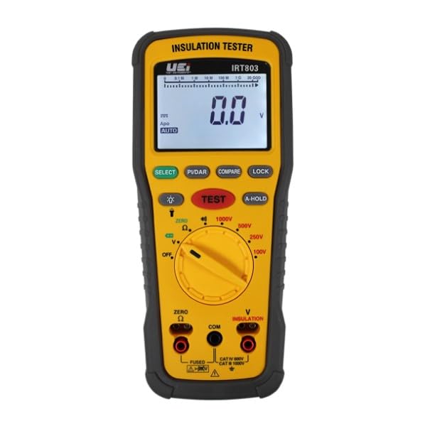
Image 10.1: Example of a Certificate of Conformity, indicating adherence to quality standards.
11. Support
For technical assistance, troubleshooting beyond this manual, or warranty claims, please contact UEi Test Instruments customer support. You can find more information and contact details by visiting the official UEi Test Instruments website or their Amazon store page.
UEi Test Instruments Store: Visit Store
Ask a question about this manual
Ask about setup, troubleshooting, compatibility, parts, safety, or missing instructions. Manuals+ will review the question and use this page’s manual context to help answer it.