1. Introduction
This manual provides essential information for the safe and efficient operation of the YWBL-WH SKI780 Variable Frequency Drive (VFD). Please read this manual thoroughly before installation, operation, or maintenance. Keep this manual for future reference.
2. Safety Information
Warning: Improper installation or operation can lead to serious injury or equipment damage. Only qualified personnel should install, operate, and maintain this device.
- Always disconnect power before performing any wiring or maintenance.
- Ensure proper grounding to prevent electric shock.
- Do not touch internal components immediately after power-off, as residual voltage may be present. Wait at least 5 minutes for capacitors to discharge.
- Install the VFD in a clean, dry, and well-ventilated environment, away from direct sunlight, corrosive gases, and excessive vibration.
- Verify that the input voltage matches the VFD's rated voltage.
3. Product Overview
3.1 Key Features
- V/F control, vector control, and output torque control.
- Integrated RS-485 communication interface.
- Equipped with a speed potentiometer and external control panel.
- Integrated synchronous control and proportional synchronization control.
- 6 speed control modes for automatic operation.
- Multiple running commands or frequency channels can be selected.
- Partial or total key locking (analog potentiometer unlock) can be achieved.
- Normally open relay and two high configuration outputs with 100 optional types.
- 6 opto-isolated digital inputs, 100 optional types.
- 3 analog inputs, 1 analog output channel.
- Textile pendulum frequency function for textile equipment applications.
- Integrated user-defined timer/counter.
- At zero speed, can produce 0-100% adjustable torque, with zero-speed braking function.
- Integrated PID regulation function for closed-loop control of temperature, pressure, and tension.
3.2 Product Appearance and Dimensions
The YWBL-WH SKI780 VFD features a compact design with an integrated control panel.
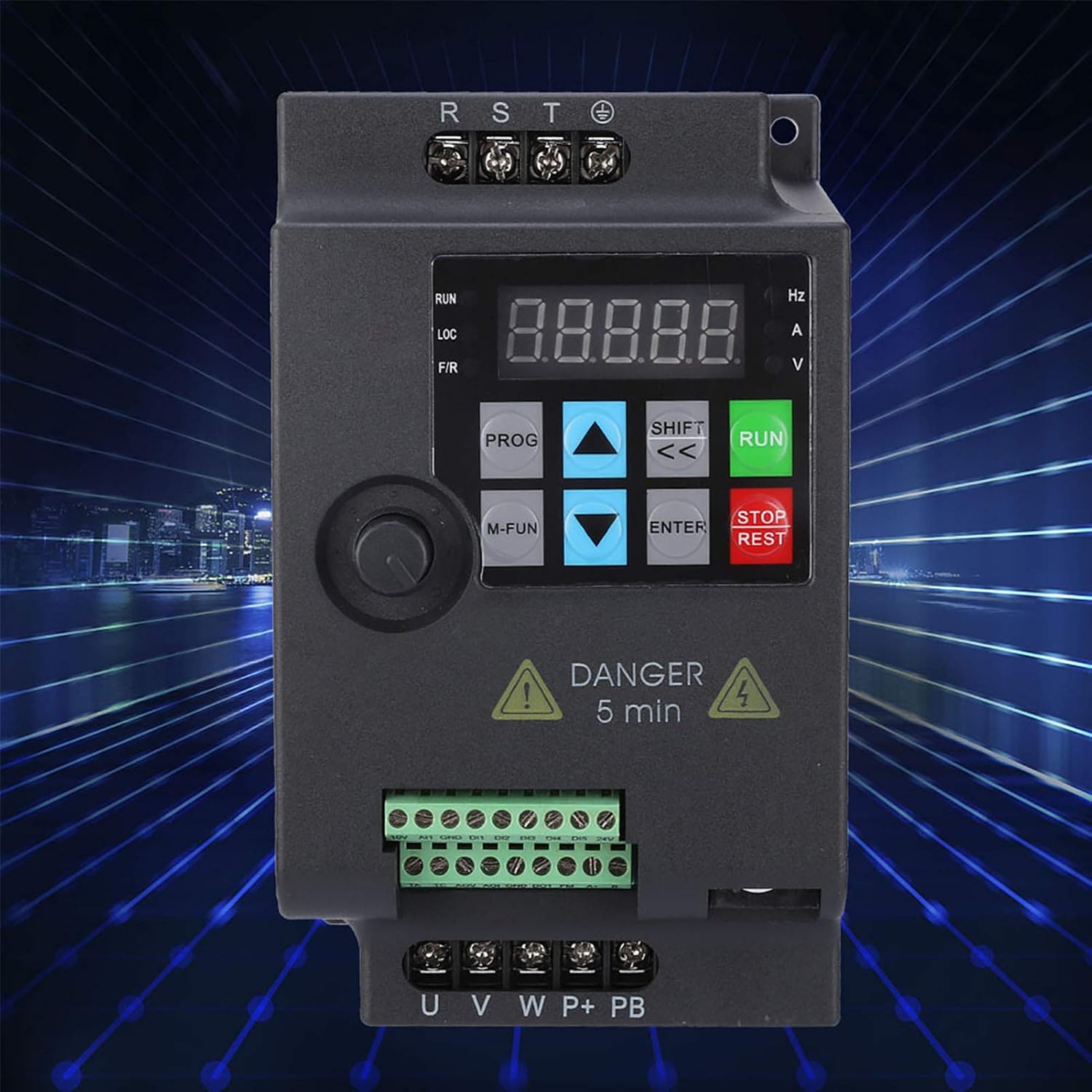

The VFD's rear panel includes mounting points for secure installation.

4. Setup and Installation
4.1 Wiring Diagram
Refer to the following diagrams for correct power and control wiring. Ensure all connections are secure and comply with local electrical codes.


4.2 Installation Environment
- Temperature: 0°C to 40°C (32°F to 104°F)
- Humidity: Less than 90% RH (non-condensing)
- Vibration: Less than 0.5G
- Altitude: Below 1000m (3300ft)
- Avoid environments with dust, metal particles, corrosive gases, or flammable materials.
5. Operating Instructions
5.1 Control Panel Functions
The VFD features an intuitive control panel for setting parameters and monitoring operation.
- PROG: Enter/Exit parameter programming mode.
- M-FUN: Multifunction key.
- UP/DOWN Arrows: Navigate through parameters and adjust values.
- SHIFT (<<): Shift cursor position during parameter editing.
- ENTER: Confirm parameter settings.
- RUN: Start motor operation.
- STOP/RESET: Stop motor operation or reset faults.
- Potentiometer: Adjust frequency/speed directly.
5.2 Basic Operation
- Power On: Connect the VFD to the appropriate power supply. The display will light up.
- Set Frequency: Use the potentiometer on the control panel or adjust the frequency parameter (e.g., F0.03) in programming mode.
- Start Motor: Press the RUN button. The motor will accelerate to the set frequency.
- Stop Motor: Press the STOP/RESET button. The motor will decelerate and stop.
- Reset Faults: If a fault occurs, the VFD will display an error code. After resolving the issue, press STOP/RESET to clear the fault.
5.3 Parameter Settings
The VFD offers a wide range of adjustable parameters to customize its operation. Refer to the detailed parameter list in the full product manual for specific settings. Common parameters include:
- F0.00: Run command source (e.g., control panel, external terminal, RS485).
- F0.01: Frequency source (e.g., potentiometer, analog input, digital setting).
- F0.03: Maximum output frequency.
- F0.04: Acceleration time.
- F0.05: Deceleration time.
- F0.06: Motor rated frequency.
- F0.07: Motor rated voltage.
- F0.08: Motor rated current.
To enter parameter programming mode, press the PROG button. Use the UP/DOWN arrows to navigate and SHIFT to select digits. Press ENTER to confirm changes.
6. Maintenance
Regular maintenance ensures the longevity and reliable operation of your VFD.
- Daily: Check for any unusual noises, vibrations, or odors. Ensure the display is functioning correctly.
- Weekly: Inspect the VFD for dust accumulation. Clean the cooling fins and fan if necessary using compressed air.
- Monthly: Check all wiring connections for tightness. Inspect for any signs of overheating or discoloration on terminals.
- Annually: Have a qualified technician perform a thorough inspection, including checking capacitor health and insulation resistance.
Caution: Always disconnect power and wait for the discharge indicator to turn off before performing any cleaning or inspection inside the VFD.
7. Troubleshooting
This section provides guidance for common issues. For complex problems, contact technical support.
| Problem | Possible Cause | Solution |
|---|---|---|
| VFD does not power on | No input power; Blown fuse; Incorrect wiring | Check power supply; Replace fuse; Verify wiring connections. |
| Motor does not run | Incorrect run command source; Fault condition; Motor wiring error | Check parameter F0.00; Clear fault; Verify motor connections (U, V, W). |
| Output frequency unstable | Interference; Loose connections; Incorrect frequency source parameter | Ensure proper shielding; Tighten connections; Check parameter F0.01. |
| Overcurrent fault (OC) | Motor overload; Short circuit; Rapid acceleration/deceleration | Reduce load; Check motor/cables; Increase acceleration/deceleration time (F0.04/F0.05). |
| Overvoltage fault (OV) | High input voltage; Rapid deceleration with high inertia load | Check input voltage; Increase deceleration time (F0.05) or install braking resistor. |
8. Specifications
The following table details the technical specifications for the YWBL-WH SKI780 3-Phase 1.5kW VFD (Model: 780-1D5-4).
| Parameter | Value |
|---|---|
| Model | SKI780-1D5G-4 |
| Rated Power | 1.5 kW |
| Input Voltage | AC 3-Phase 380V ±15% |
| Input Current | 5A |
| Input Frequency | 47Hz - 63Hz |
| Output Voltage | AC 3-Phase 0V - 380V |
| Output Current | 3.8A |
| Output Frequency | 0Hz - 400Hz |
| Control Mode | Current Vector Control, V/F Control |
| Output Voltage Regulation Mode | PWM Control |
| Dimensions (L x W x H) | 142mm x 85mm x 110mm (5.6 x 3.3 x 4.3 inches) |
| Weight | Approx. 1000-1042g (35.3-36.7 oz) |
| Recommended Motor Power | 1.5 kW (2 HP) |
| Communication Interface | RS-485 |
9. Warranty and Support
For warranty information, technical support, or service inquiries, please contact your original point of purchase or the manufacturer directly. Ensure you have your product model number (SKI780-1D5G-4) and serial number (if applicable, e.g., H00150400468) ready when contacting support.