Envertech ET99300009002
Envertech EVT300 Micro-Inverter User Manual
Model: ET99300009002
Brand: Envertech
Introduction
This manual provides essential information for the safe and efficient operation of your Envertech EVT300 Micro-Inverter. The EVT300 is designed to convert direct current (DC) from a single solar module into alternating current (AC) for grid connection, suitable for mini-PV and balcony power plant applications. Please read this manual thoroughly before installation and use to ensure proper functionality and safety.
Safety Information
WARNING: Electrical Hazard!
- Installation and maintenance must be performed by qualified personnel only.
- Always disconnect all power sources (AC and DC) before servicing the inverter or making any connections.
- Ensure compliance with all applicable national and local electrical codes, regulations, and grid operator requirements during installation and operation.
- Do not attempt to open, disassemble, or repair the inverter yourself. Contact qualified service personnel for any repairs.
- The inverter may become hot during operation. Avoid direct contact with the inverter's surface to prevent burns.
- Ensure proper grounding of the inverter.
Package Contents
Verify that all items are present in the package:
- Envertech EVT300 Micro-Inverter (1 unit)
Product Overview
The Envertech EVT300 is a compact and efficient micro-inverter designed for individual solar module optimization. It features an integrated NA-protection according to VDE-AR-N 4105, ensuring safe grid connection. The device is built to maximize energy harvest from each PV module with 48-72 cells.

Figure 1: Front view of the Envertech EVT300 Micro-Inverter, showing the main unit with the Envertech logo and connected cables for DC input and AC output.
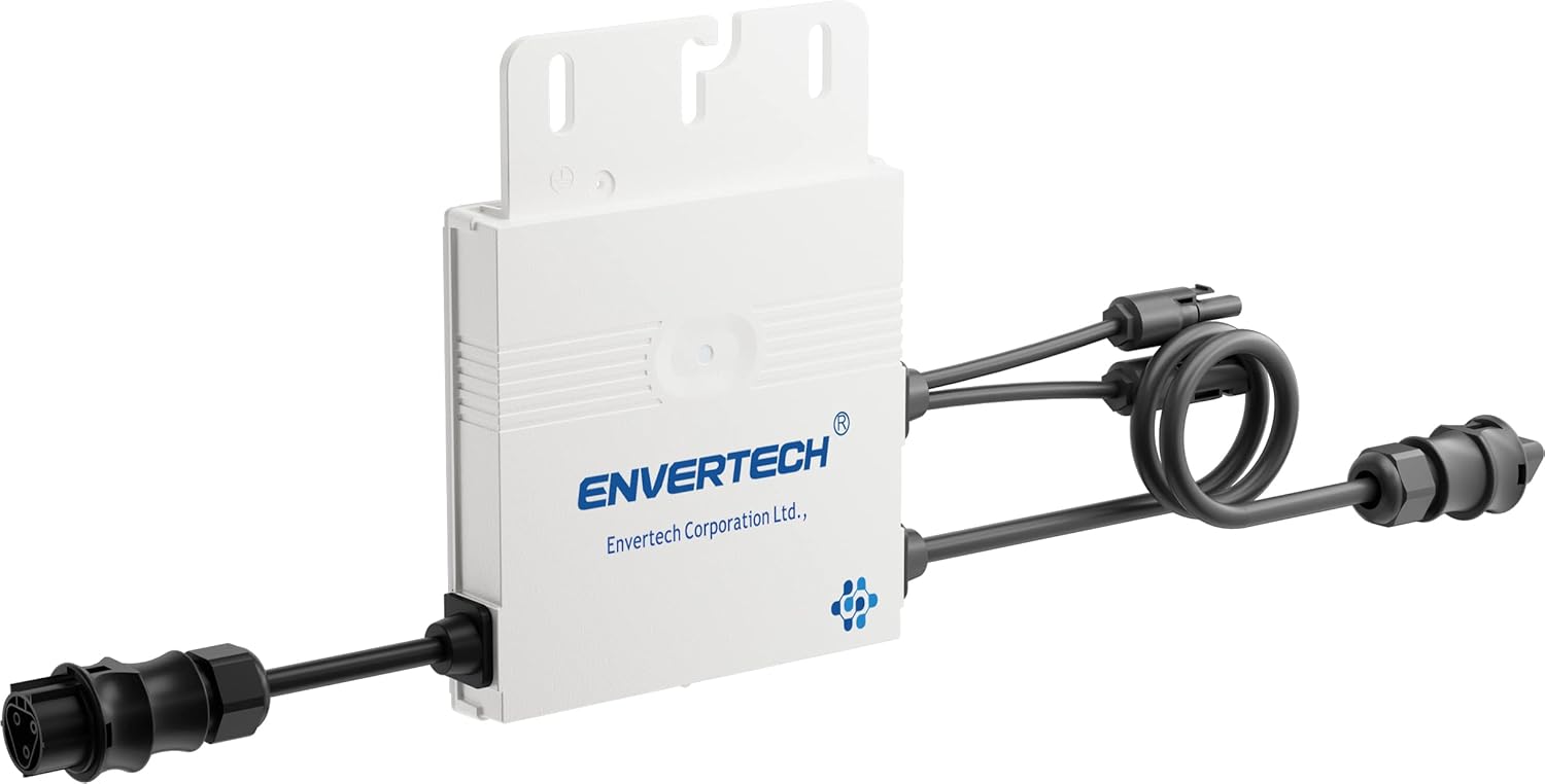
Figure 2: Angled view of the Envertech EVT300 Micro-Inverter, highlighting the cable connections and mounting points on the top of the unit.
Installation Guide
1. Site Selection
Choose a mounting location that is well-ventilated, protected from direct sunlight, and extreme weather conditions. Ensure the location allows for easy access for future maintenance and inspection.
2. Mounting the Inverter
Securely mount the inverter to a stable structure using appropriate fasteners. Ensure the inverter is mounted in an orientation that facilitates optimal heat dissipation, typically with the cooling fins vertical.
3. Electrical Connections
- Connect the DC input cables from the solar module(s) to the DC input terminals of the inverter. Observe correct polarity (+ to + and - to -).
Important: Ensure the connected solar module meets the following requirements: Open Circuit Voltage (Uoc) less than 51.7 Volts; Short Circuit Current (Isc) less than 14.7 Amperes; MPP Voltage (Umpp) greater than 27.1 Volts; and a minimum power output greater than 180 Watts.
- Connect the AC output cable from the inverter to your electrical grid connection point. The inverter is equipped with a Betteri BC01 connector for grid connection.
- Ensure all electrical connections are tight, secure, and properly insulated to prevent short circuits or electrical hazards.
4. Grounding
Properly ground the inverter according to all local electrical codes and regulations to ensure safety and prevent electrical shock.
5. Power On
After all connections have been thoroughly checked and verified for correctness and security, switch on the AC circuit breaker, followed by any DC disconnects (if applicable). The inverter will then initiate its startup sequence.
Operation
Startup Sequence
Upon receiving power, the inverter will perform a series of self-tests and grid checks to ensure safe and compliant operation. This startup process typically takes a few minutes.
Power Generation
Once the self-test is successfully completed and sufficient solar power is available from the connected module(s), the inverter will automatically begin converting DC power into AC power and feeding it into the electrical grid.
Status Indicator (LED)
The inverter is equipped with an LED indicator that provides visual feedback on its operational status:
- Green LED blinking: This indicates that the inverter is actively producing and feeding power into the grid. Each blink typically represents approximately 25 Watts of power output (e.g., 1 blink = 25W, 2 blinks = 50W, 4 blinks = 100W).
- Other LED states: For other LED patterns or colors, please refer to the troubleshooting section for potential error codes or abnormal operating conditions.
Maintenance
The Envertech EVT300 Micro-Inverter is designed for reliable operation with minimal maintenance requirements. Adhering to the following guidelines will help ensure its longevity and performance:
- Regular Inspection: Periodically inspect the inverter and all associated wiring and connections for any visible signs of damage, corrosion, wear, or loose connections. Address any issues promptly.
- Cleaning: Keep the inverter's exterior clean and free of dust, dirt, and debris. Use a soft, dry cloth for cleaning. Do not use abrasive cleaners, solvents, or liquids directly on the inverter.
- Ventilation: Ensure that the inverter's ventilation openings are not obstructed by dirt, debris, or other objects. Proper airflow is crucial for effective heat dissipation and optimal performance.
WARNING: Always disconnect all AC and DC power sources to the inverter before performing any maintenance or cleaning procedures.
Troubleshooting
This section provides solutions to common issues you might encounter with your Envertech EVT300 Micro-Inverter. If the problem persists after attempting these solutions, please contact customer support.
| Problem | Possible Cause | Solution |
|---|---|---|
| Inverter not producing power (LED off or red) | No DC input from solar module; AC grid not connected or power outage; Internal fault. | Check solar module connections and ensure sufficient sunlight. Verify AC grid connection and circuit breaker. If problem persists, contact support. |
| Low power output | Insufficient sunlight; Shading on solar module; Module not meeting specifications; Dirty solar module. | Ensure module is in full sun. Check for any shading. Verify module specifications against inverter requirements. Clean solar module surface. |
| Inverter makes unusual noises | Internal component issue. | Disconnect power immediately and contact customer support. Do not attempt to operate the inverter. |
| Inverter gets excessively hot | Poor ventilation; Overload; High ambient temperature. | Ensure adequate airflow around the inverter. Check if the connected module's power exceeds the inverter's rating. Relocate if ambient temperature is consistently too high. |
Technical Specifications
| Parameter | Value |
|---|---|
| Model | EVT300 |
| Part Number | ET99300009002 |
| Rated Power Output | 300 Watts |
| Input Voltage (Open Circuit Voltage Uoc) | Less than 51.7 Volts |
| Input Current (Short Circuit Current Isc) | Less than 14.7 Amperes |
| MPP Voltage (Umpp) | Greater than 27.1 Volts |
| Recommended Module Power | Greater than 180 Watts |
| Connector Type | Betteri BC01 |
| Item Weight | 1.8 Kilograms |
| Product Dimensions (L x W x H) | 40.64 x 31.24 x 4.4 cm |
| Power Source | Plug |
Warranty and Support
Warranty Information
For detailed warranty terms and conditions applicable to your Envertech EVT300 Micro-Inverter, please refer to the warranty documentation provided at the time of purchase or contact your authorized retailer.
Customer Support
If you encounter any issues, have questions not covered in this manual, or require technical assistance, please contact Envertech customer support or your authorized dealer for professional help.
Manufacturer: Envertech SEEYES
Ask a question about this manual
Ask about setup, troubleshooting, compatibility, parts, safety, or missing instructions. Manuals+ will review the question and use this page’s manual context to help answer it.