1. Product Overview
This manual provides detailed instructions for the installation, operation, and maintenance of The ROP Shop Dual Lever Binnacle Mount Remote Control Assembly. This unit is designed to provide precise control over your Johnson & Evinrude outboard motor's throttle and shift functions. Please review all information carefully before installation and use to ensure proper function and safety.
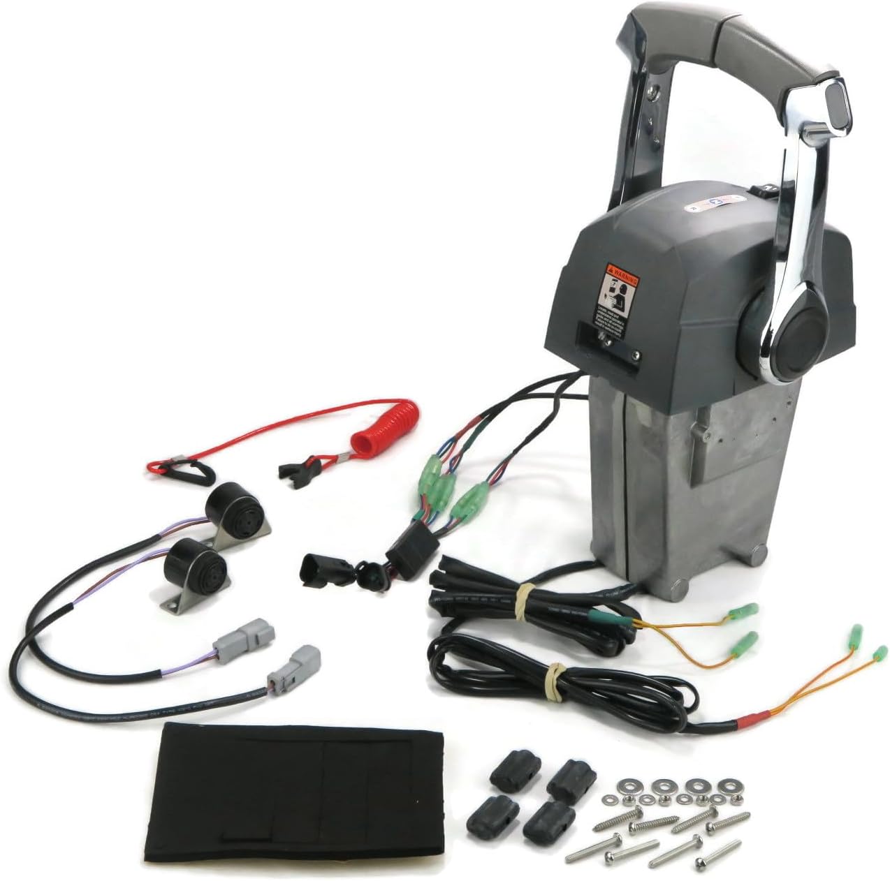
Figure 1.1: Complete Remote Throttle Control Assembly with included components.
2. Components Included
The package includes the following components:
- (1) Remote Control Assembly (Dual Lever Binnacle Mount)
- (1) Instruction/Installation Manual (this document)
- Hardware for mounting and connection
- Wiring harnesses and connectors
- Kill switch lanyard
Note: Standard shift and throttle cables (1979 and newer type) are NOT included and must be purchased separately.
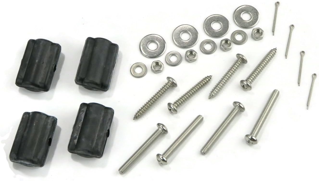
Figure 2.1: Mounting hardware including screws, washers, and nuts.
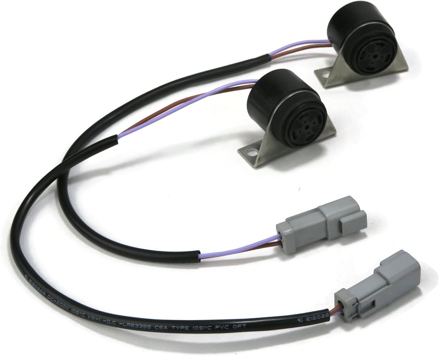
Figure 2.2: Various wiring harnesses and connectors for electrical integration.
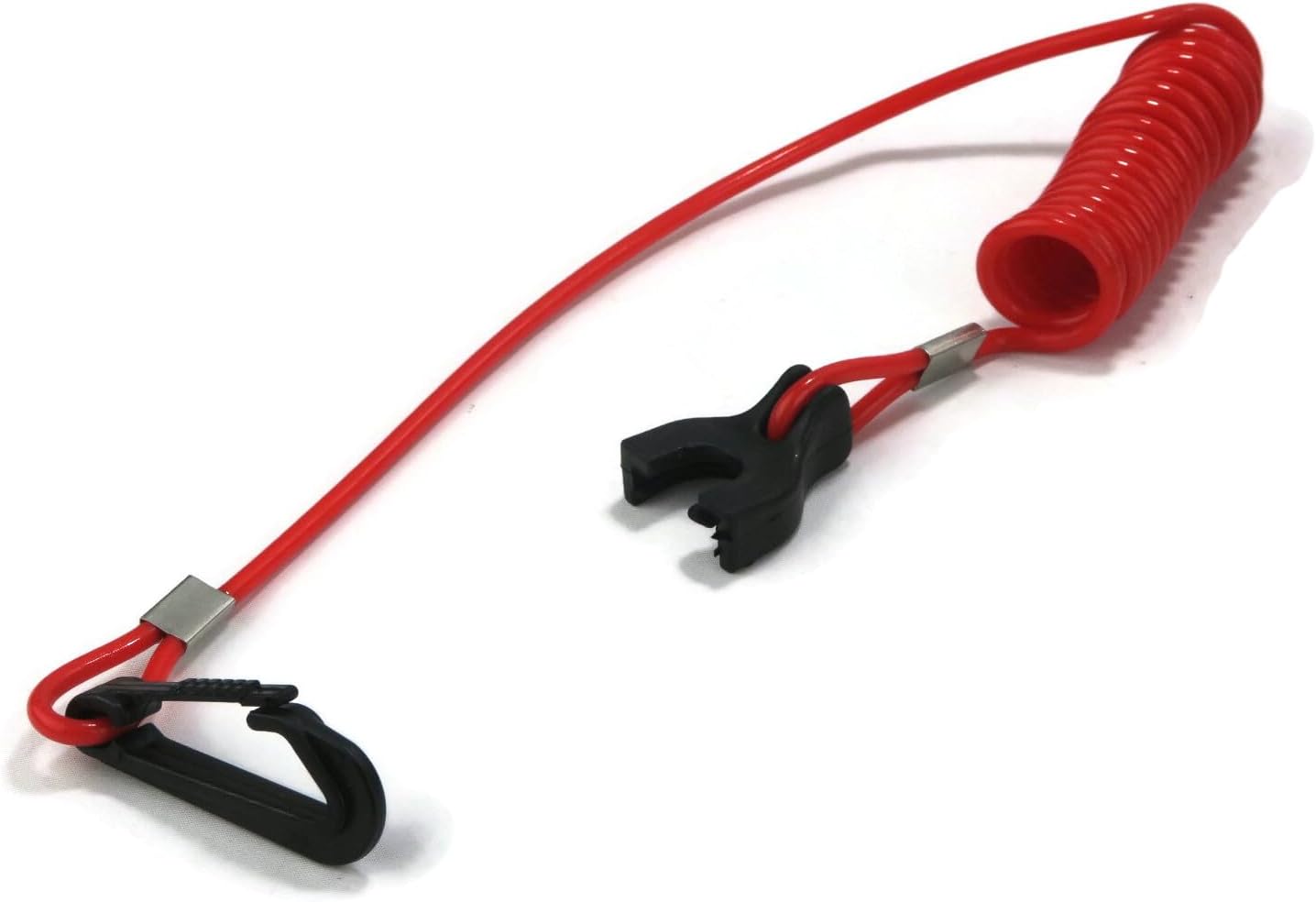
Figure 2.3: Safety kill switch lanyard.
3. Specifications
| Model Number | 100623 |
| Type | Dual Lever Binnacle Mount Remote Control |
| Compatibility | Johnson & Evinrude Outboard Motors (with 1979 and newer type cables) |
| Dimensions (Approx.) | 21 x 17 x 7 inches (Item Package Dimensions) |
| Weight (Approx.) | 15.16 Pounds (Item Weight) |
| Features | Neutral Detent, "Start in gear prevention" switch, Adjustable throttle friction |
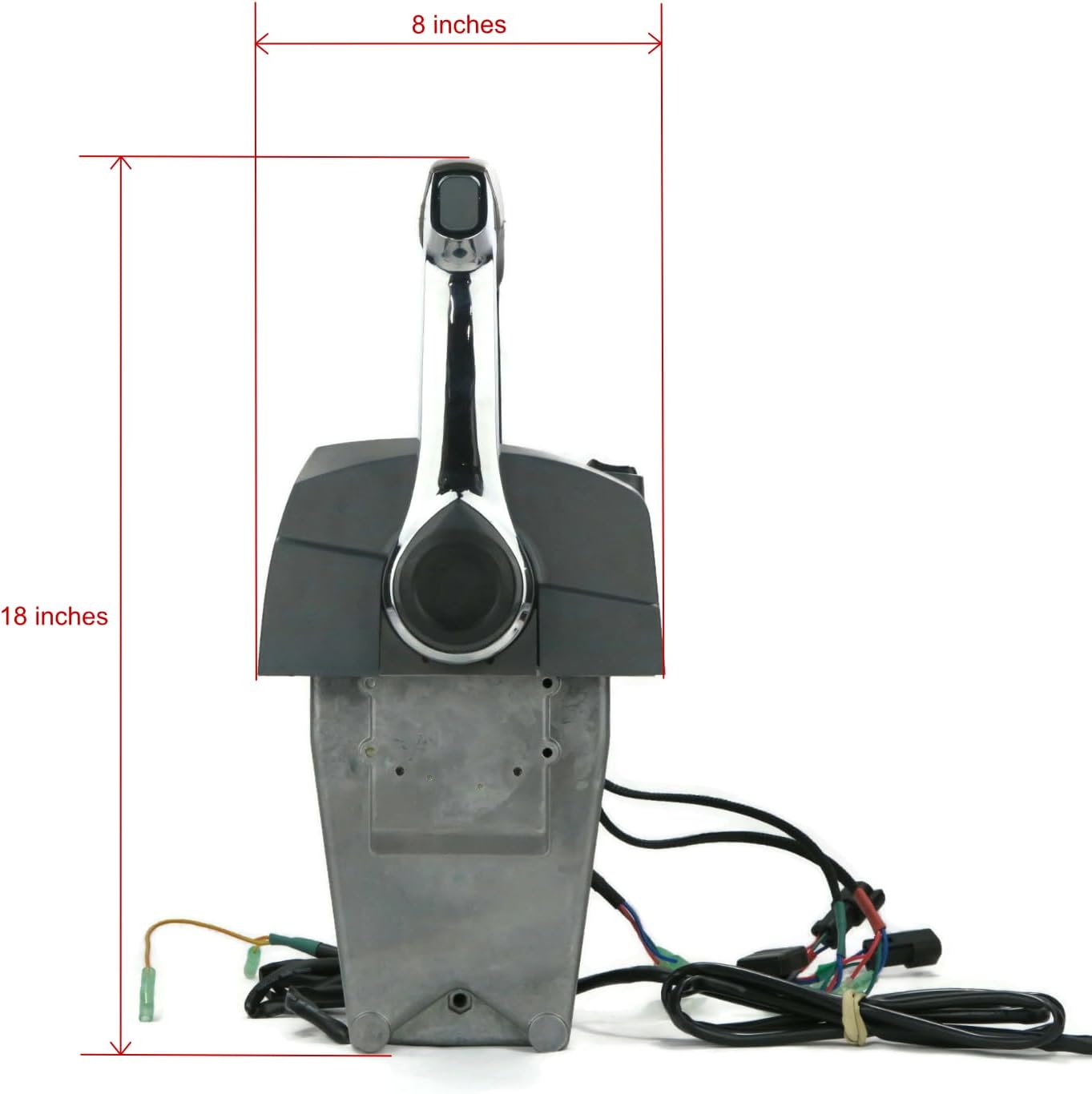
Figure 3.1: Side view illustrating approximate height (18 inches) and depth (8 inches).
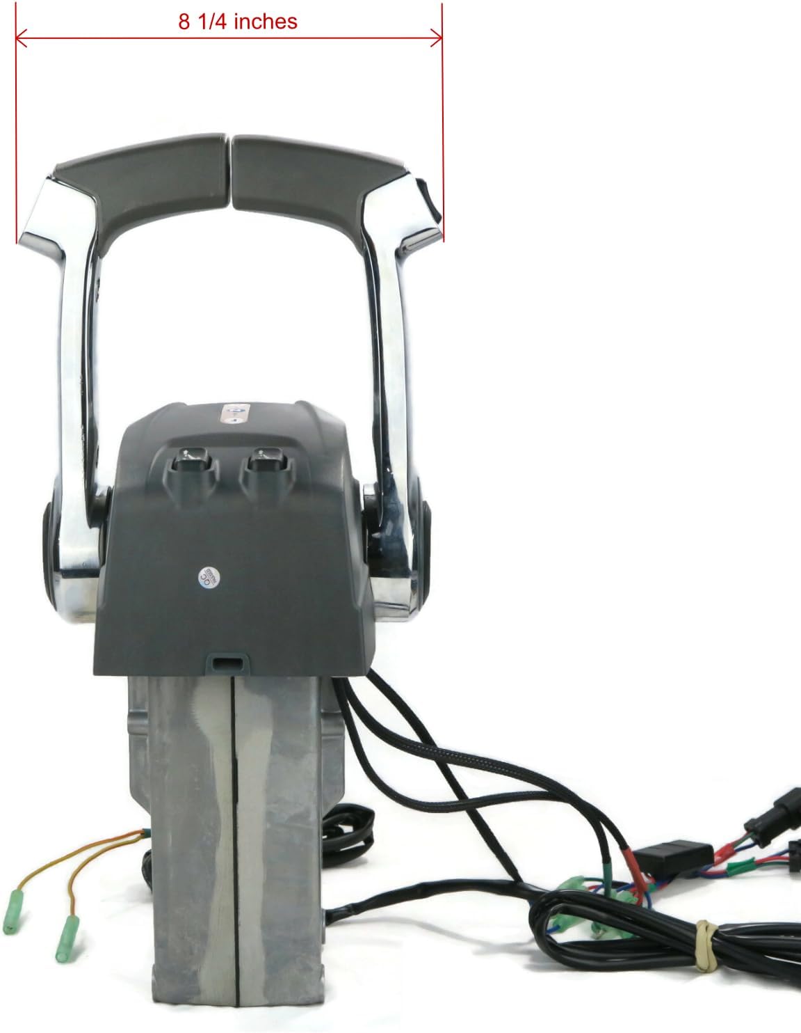
Figure 3.2: Top view illustrating approximate width (8 1/4 inches) of the control levers.
4. Setup and Installation
Proper installation is crucial for the safe and effective operation of your remote control. If you are unsure about any step, it is recommended to consult a qualified marine technician.
4.1 Mounting the Control Unit
- Select Location: Choose a suitable binnacle mounting location on your boat that allows for comfortable operation and clear visibility of the controls. Ensure there is sufficient space behind the mounting surface for wiring and cable routing.
- Prepare Mounting Surface: Mark the drilling points using the control unit as a template. Drill appropriate pilot holes for the mounting hardware.
- Secure Unit: Attach the remote control unit to the binnacle using the provided mounting hardware (screws, washers, nuts). Ensure it is securely fastened to prevent movement during operation.
4.2 Connecting Shift and Throttle Cables
This unit uses standard shift and throttle cables (1979 and newer type). Refer to your outboard motor's manual for specific cable routing and connection points on the engine side.
- Route Cables: Carefully route the shift and throttle cables from the control unit to the outboard motor, avoiding sharp bends or obstructions.
- Connect to Control Unit: Attach the cable ends to the appropriate mechanisms within the remote control unit. Ensure smooth movement of the levers translates directly to cable movement.
- Connect to Engine: Connect the other ends of the cables to the shift and throttle linkages on your outboard motor as per the engine manufacturer's instructions.
- Adjust Cables: Adjust cable tension and length to ensure full range of motion for both shift and throttle, and that the neutral detent engages correctly.
4.3 Electrical Connections
The control unit includes wiring for various functions such as the "start in gear prevention" switch and potentially other auxiliary functions. Refer to your outboard motor's wiring diagram for specific connections.
- Identify Wires: Match the wires from the control unit's harness to the corresponding wires on your outboard motor's harness. Color coding is typically used.
- Connect Wires: Use appropriate marine-grade connectors (crimp connectors, heat shrink tubing) to ensure secure and waterproof connections.
- Connect Kill Switch: Install the kill switch lanyard mechanism and connect its wiring to the designated safety circuit on your engine.
- Test Connections: Before operating, perform a thorough test of all electrical connections to ensure proper function of the "start in gear prevention" switch and other electrical components.
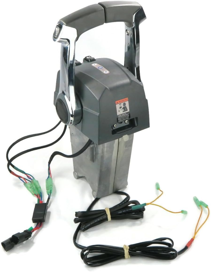
Figure 4.1: Front view of the control unit showing main wiring harness connections.
5. Operating Instructions
Familiarize yourself with the control unit's functions before operating your vessel.
5.1 Throttle and Shift Operation
- Neutral Position: The control levers will have a distinct "neutral detent" position. This is the starting point for all operations. The engine should only start when the levers are in this neutral position, thanks to the "start in gear prevention" switch.
- Shifting Gears:
- To engage Forward gear, push the appropriate lever forward from the neutral detent.
- To engage Reverse gear, pull the appropriate lever backward from the neutral detent.
- Ensure the gear is fully engaged before applying significant throttle.
- Throttle Control: Once a gear is engaged, further movement of the lever in the same direction will increase engine RPM (throttle).
- Adjustable Throttle Friction: The control unit features adjustable throttle friction. This allows you to set the resistance of the throttle lever to your preference, preventing accidental throttle changes due to vibration or rough water. Adjust as needed for comfortable and precise control.
5.2 Kill Switch Lanyard
Always attach the kill switch lanyard to yourself or your clothing before starting the engine. In the event of the operator being thrown from the helm, the lanyard will pull the kill switch, immediately stopping the engine and preventing a runaway boat.
6. Maintenance
Regular maintenance will ensure the longevity and reliable operation of your remote throttle control unit.
- Cleaning: Periodically clean the exterior of the control unit with a mild soap and fresh water. Avoid harsh chemicals or abrasive cleaners.
- Lubrication: Apply a marine-grade grease or lubricant to the moving parts of the shift and throttle mechanisms annually, or more frequently in saltwater environments.
- Cable Inspection: Regularly inspect the shift and throttle cables for signs of fraying, corrosion, or damage. Replace damaged cables immediately.
- Electrical Connections: Check all electrical connections for corrosion or looseness. Clean and re-secure as necessary.
- Fastener Check: Ensure all mounting fasteners are tight. Do not overtighten.
7. Troubleshooting
If you encounter issues with your remote control unit, refer to the following common problems and solutions:
| Problem | Possible Cause | Solution |
|---|---|---|
| Engine does not start in neutral. | "Start in gear prevention" switch malfunction or misadjustment. | Check switch wiring and adjustment. Ensure levers are fully in neutral detent. |
| Difficulty shifting gears. | Stiff or corroded shift cables; misadjusted cables; internal control unit issue. | Inspect and lubricate cables. Adjust cable tension. If problem persists, consult a technician. |
| Throttle not responding or sticking. | Stiff or corroded throttle cable; misadjusted throttle friction; internal control unit issue. | Inspect and lubricate cable. Adjust throttle friction. If problem persists, consult a technician. |
| Kill switch not functioning. | Lanyard not properly attached; faulty switch or wiring. | Ensure lanyard is correctly inserted. Check kill switch wiring. Replace if faulty. |
For issues not listed here or if solutions do not resolve the problem, please contact customer support.
8. Warranty Information
This product is covered by a 1-Year Warranty from the date of purchase. This warranty covers defects in materials and workmanship under normal use. It does not cover damage resulting from improper installation, misuse, neglect, accident, or unauthorized repairs.
Please retain your proof of purchase for warranty claims. For detailed warranty terms and conditions, or to initiate a warranty claim, please contact The ROP Shop customer service.
9. Customer Support
If you require assistance with your Remote Throttle Control, have questions about compatibility, or need troubleshooting help, please contact The ROP Shop customer support.
When contacting support, please be prepared to provide the following information:
- Product Model Number (100623)
- Date of Purchase
- A detailed description of the issue
- Your outboard motor's model and serial number (if applicable)
For contact information, please visit The ROP Shop's official website or refer to the packaging.