1. Product Overview
The Walfront IP65 G3/8 Analog Pressure Sensor is a high-precision device designed for industrial applications requiring accurate pressure measurement. It features a robust stainless steel shell, an advanced ceramic core, and a customized process chip for stable and reliable performance. This sensor is equipped with EMC protection and offers easy operation due to its compact and lightweight design, ensuring low long-term drift.

Figure 1: Close-up view of the Walfront IP65 G3/8 Analog Pressure Sensor, showing the G3/8 screw fitting and the cable connection point. This image highlights the robust construction and connection interface of the sensor.
2. Technical Specifications
| Feature | Specification |
|---|---|
| Protection Level | IP65 |
| Input Voltage | 5 ± 0.25 VDC / 5 ~ 32 VDC |
| Technology | Piezo-resistance |
| Screw Fitting | G3/8 |
| Output Signal | Analog Signal |
| Measurement Range | 0 ~ 10 BAR |
| Output Model | Three-wire |
| Overpressure | 2 times full pressure range |
| Burst Pressure | 3 times full pressure range |
| Full Scale Accuracy (Non-linearity + Repeatability + Hysteresis) | ± 1% FS (0 ~ 80°C), ± 1.5% FS (-20 ~ 100°C), ± 3% FS (-40 ~ 125°C) |
| Electrical Connection | Compatible with Packard connector (three conductors) |
| Material | Stainless Steel, Ceramic |
| Model Number | SEAFRONToewafv0c9q-03 |
| UPC | 724316058530 |
3. Setup and Installation
Before installation, ensure that the power supply is disconnected from the system where the sensor will be integrated. Verify that the pressure range of the sensor (0-10 BAR for this model) matches the requirements of your application.
- Mechanical Installation:
The sensor features a G3/8 screw fitting. Carefully thread the sensor into the designated pressure port. Ensure a tight seal using appropriate sealing tape or compound if necessary, to prevent leaks. Do not overtighten, as this may damage the sensor or the port.

Figure 2: The G3/8 screw fitting of the pressure sensor, ready for mechanical installation into a compatible port. This image emphasizes the connection type.
- Electrical Connection:
The sensor uses a three-wire electrical connection, compatible with a Packard connector. Identify the power supply (VCC), ground (GND), and analog output signal (OUT) wires. Connect them according to your system's wiring diagram. Ensure correct polarity to prevent damage.
- Red Wire: Power Supply (5 ± 0.25 VDC or 5 ~ 32 VDC)
- Black Wire: Ground (GND)
- Green/Blue Wire: Analog Output Signal

Figure 3: The Walfront pressure sensor showing its three-wire cable connection. This image illustrates the wiring for electrical integration.
- Power On and Testing:
After securing both mechanical and electrical connections, apply power to the system. Monitor the analog output signal to ensure it responds correctly to pressure changes. Initial calibration or verification with a known pressure source is recommended.
4. Operating Instructions
The Walfront IP65 G3/8 Analog Pressure Sensor operates by converting applied pressure into a proportional analog electrical signal. This signal can then be read by a compatible control system, PLC, or data acquisition unit.
- Signal Interpretation: The analog output signal will vary linearly with the applied pressure within the specified measurement range (0-10 BAR). Refer to your system's documentation for converting the analog voltage or current into pressure units.
- Environmental Conditions: Ensure the sensor operates within its specified temperature range (-40°C to 125°C) and protection level (IP65). Avoid exposing the sensor to corrosive substances or extreme vibrations that could affect its performance or lifespan.
- Overpressure Protection: The sensor is designed to withstand overpressure up to 2 times its full pressure range and burst pressure up to 3 times. However, continuous operation beyond the rated measurement range is not recommended and may lead to reduced accuracy or damage.
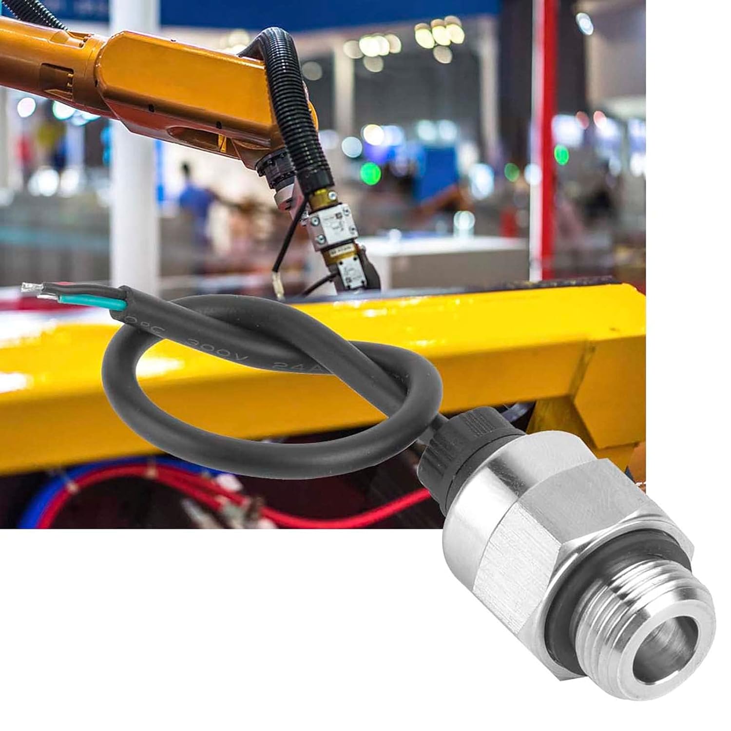
Figure 4: The pressure sensor shown in an industrial setting, integrated with a robotic arm. This demonstrates a typical application environment for the sensor.
5. Maintenance
The Walfront IP65 G3/8 Analog Pressure Sensor is designed for low maintenance. Regular checks can help ensure its longevity and accurate performance.
- Visual Inspection: Periodically inspect the sensor for any signs of physical damage, corrosion, or loose connections. Ensure the cable insulation is intact.
- Cleaning: If necessary, gently clean the exterior of the sensor with a soft, damp cloth. Do not use abrasive cleaners or solvents that could damage the stainless steel housing or seals.
- Recalibration: For critical applications, periodic recalibration by a qualified technician is recommended to maintain optimal accuracy. The frequency of recalibration depends on the application's demands and environmental conditions.
6. Troubleshooting
If you encounter issues with your Walfront IP65 G3/8 Analog Pressure Sensor, refer to the following common problems and solutions:
| Problem | Possible Cause | Solution |
|---|---|---|
| No output signal |
|
|
| Inaccurate readings |
|
|
| Intermittent signal |
|
|
7. Warranty and Support
For warranty information or technical support regarding your Walfront IP65 G3/8 Analog Pressure Sensor, please refer to the documentation provided at the time of purchase or contact your vendor. Ensure you have your model number (SEAFRONToewafv0c9q-03) and UPC (724316058530) available when seeking support.