1. Introduction
This manual provides comprehensive instructions for the installation, operation, and maintenance of the Keenso REX-C100FK02-M*AN PID Digital Temperature Controller. This device is designed for precise temperature regulation in various applications, featuring a wide measuring range and PID self-identification functionality.
Please read this manual thoroughly before operating the device to ensure safe and efficient use.
2. Product Overview
2.1 Key Features
- Wide Application: Suitable for vegetable greenhouses, domestic water tanks, aquariums, aquaculture, and other temperature-controlled systems.
- Clear Screen Display: Features a clear screen for enhanced readability of temperature values.
- Wide Measuring Range: Capable of measuring temperatures from 0 to 400℃.
- PID Self-Identification: Incorporates PID self-identification function for optimized control performance.
- Output Type: Relay output.
- Supply Voltage: 100-240V AC, 50/60Hz.
2.2 Components
The Keenso REX-C100FK02-M*AN temperature controller consists of the main unit with a digital display and control buttons, and terminal blocks for electrical connections.
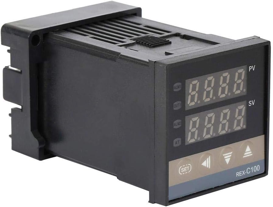
Figure 2.1: Front-side view of the Keenso REX-C100FK02-M*AN PID Digital Temperature Controller. The device features a black casing with two digital displays (PV and SV) and control buttons below.

Figure 2.2: Close-up view of the controller's front panel, showing the PV (Process Value) and SV (Set Value) displays, along with ALM1, OUT1, ALM2, AT indicators, and SET, left arrow, down arrow, and up arrow buttons.

Figure 2.3: Composite image showing the front, side, and rear terminal block views of the REX-C100 controller, highlighting its compact design and connection points.
3. Specifications
| Parameter | Value |
|---|---|
| Model Number | REX-C100FK02-M*AN (Item model number: Kee nso1um2sx0adb) |
| Display Type | LCD |
| Operating Temperature Range | 0-400℃ (4E+2 Degrees Celsius) |
| Voltage | 100-240V AC |
| Frequency | 50/60Hz |
| Output Type | Relay |
| Material | Metal |
| Product Dimensions | 3.94 x 1.97 x 1.97 inches (1.89"L x 1.89"W x 1.9"H) |
| Item Weight | 5.3 ounces (0.15 Kilograms) |
| Batteries Required | No |
| UPC | 712979133626 |

Figure 3.1: Side view of the REX-C100 controller illustrating its physical dimensions, approximately 48mm (1.9 inches) in width and height.
4. Setup and Installation
4.1 Safety Precautions
- Ensure power is disconnected before any installation or wiring.
- All wiring should be performed by a qualified electrician or technician.
- Verify that the supply voltage matches the controller's specifications (100-240V AC).
- Avoid installing the controller in areas with excessive moisture, dust, or corrosive gases.
4.2 Mounting
The REX-C100 is designed for panel mounting. Cut an appropriate opening in your control panel according to the product dimensions (approximately 48x48mm or 1.89x1.89 inches). Insert the controller into the opening and secure it using the provided mounting clips.
4.3 Wiring Diagram
Refer to the wiring diagram located on the side label of the controller for correct connections. The main connections typically include power supply, sensor input (e.g., K-type thermocouple), and relay output for controlling the heating/cooling element.

Figure 4.1: Detailed view of the product label on the side of the controller, which includes the model number, range, output type (RELAY), and a simplified wiring diagram for power supply (100-240VAC) and output connections.
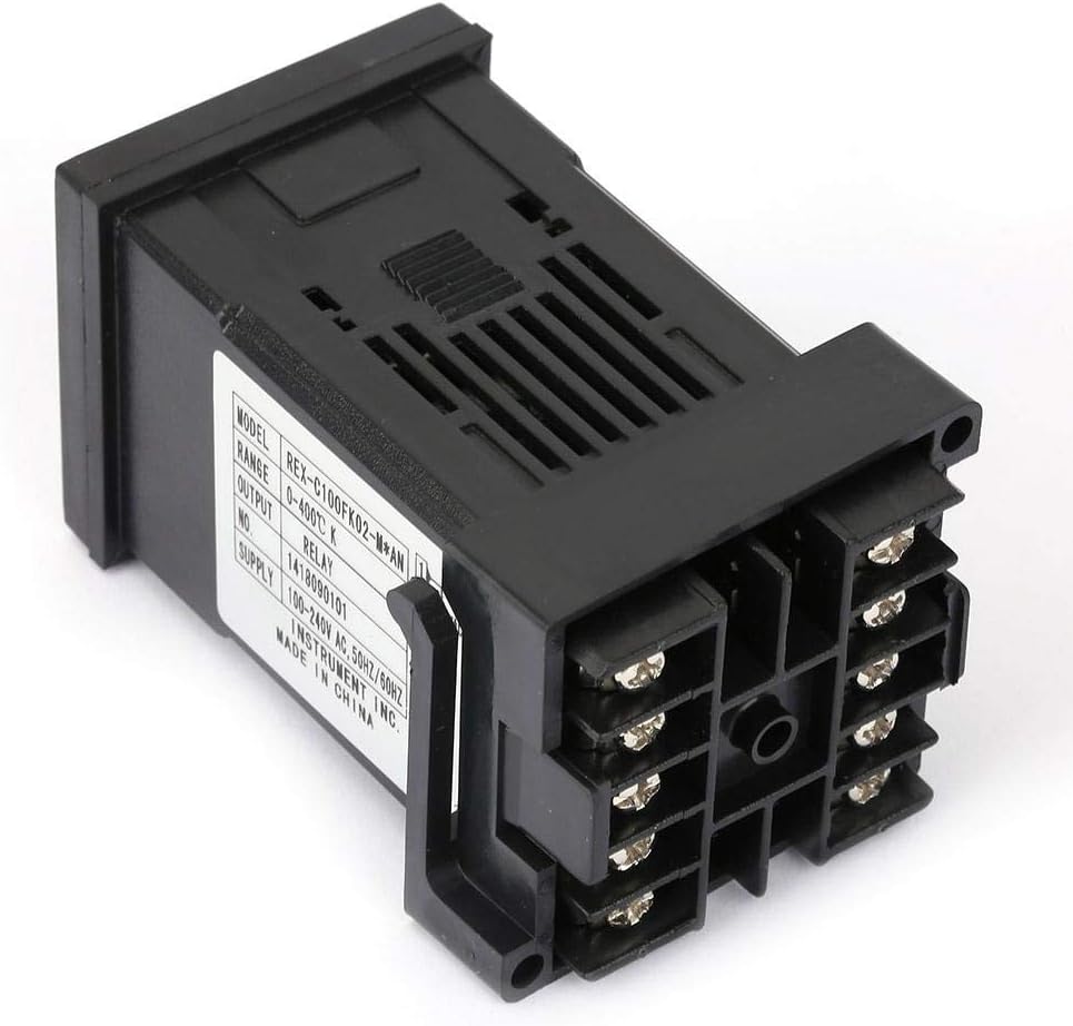
Figure 4.2: Rear view of the REX-C100 controller, clearly showing the screw terminal blocks for electrical connections. These terminals are used for power input, sensor input, and relay output.
- Power Supply (Pins 1 & 2): Connect your 100-240V AC power source to these terminals.
- Relay Output (Pins 3 & 4): These are the contacts for the control output. Connect your heating or cooling element through these contacts.
- Sensor Input (Pins 5 & 6): Connect your K-type thermocouple or other compatible temperature sensor here. Ensure correct polarity if applicable.
Note: The exact pin assignments may vary slightly based on specific model revisions. Always refer to the label on your specific unit.
5. Operating Instructions
5.1 Display Overview
- PV (Process Value): Displays the current measured temperature.
- SV (Set Value): Displays the desired target temperature.
- ALM1/ALM2: Alarm indicators.
- OUT1: Output indicator, illuminates when the control output is active.
- AT: Auto-tuning indicator, illuminates during PID self-identification.
5.2 Basic Operation
- Power On: After correct wiring, apply power to the controller. The PV display will show the current temperature, and the SV display will show the last set temperature.
- Setting the Target Temperature (SV):
- Press the SET button once. The SV display will begin to flash.
- Use the Up (▲) and Down (▼) arrow buttons to adjust the target temperature.
- Use the Left Arrow (◀) button to shift the digit for faster adjustment.
- Press SET again to confirm the new target temperature.
- Monitoring: The controller will automatically regulate the temperature to maintain the SV. The OUT1 indicator will show when the output relay is engaged.
5.3 PID Self-Identification (Auto-Tuning)
The PID self-identification (auto-tuning) function helps the controller determine optimal PID parameters for your specific system, leading to more stable and accurate temperature control.
- Set the desired target temperature (SV) as described in section 5.2.
- Press and hold the SET button for approximately 3-5 seconds until the parameter menu appears.
- Navigate through the parameters until you find the auto-tuning parameter (often labeled "AT" or similar).
- Change the value of this parameter to "1" (or "ON") to initiate auto-tuning. The AT indicator will illuminate.
- The controller will cycle the output to analyze the system's thermal response. This process may take some time, and the temperature may overshoot or undershoot the SV during tuning.
- Once auto-tuning is complete, the AT indicator will turn off, and the controller will operate with the newly calculated PID parameters.
- Caution: For systems with low thermal mass and quick heating times, the overshoot during auto-tuning can be significant. Consider performing auto-tuning at a lower, safer temperature if this is a concern.
6. Maintenance
- Cleaning: Keep the controller's display and casing clean using a soft, dry cloth. Do not use abrasive cleaners or solvents.
- Connections: Periodically check all electrical connections to ensure they are secure and free from corrosion.
- Environment: Ensure the operating environment remains within specified conditions (temperature, humidity) to prolong the life of the device.
- No User-Serviceable Parts: The internal components of the controller are not user-serviceable. Do not attempt to open or repair the unit yourself.
7. Troubleshooting
| Problem | Possible Cause | Solution |
|---|---|---|
| Controller does not power on. | No power supply; incorrect wiring; faulty unit. | Check power connections and voltage. Verify wiring against diagram. If issues persist, contact support. |
| PV display shows "HHHH" or "LLLL". | Sensor open circuit; sensor short circuit; sensor out of range; incorrect sensor type. | Check sensor wiring and connections. Ensure sensor is compatible and within operating range. Replace faulty sensor. |
| Temperature control is unstable or inaccurate. | PID parameters not optimized; external disturbances; incorrect sensor placement. | Perform PID self-identification (auto-tuning). Ensure sensor is correctly placed and insulated. Minimize drafts or rapid temperature changes. |
| Output (OUT1) indicator does not light up. | SV is already met; output relay faulty; wiring issue to load. | Check if PV is at SV. Verify wiring to the heating/cooling element. If the problem persists, the internal relay may be faulty. |
8. Warranty and Support
Keenso is committed to providing customer satisfaction. If you encounter any issues or have questions regarding your REX-C100FK02-M*AN temperature controller, please contact our customer support team.
We aim to resolve all issues within 24 hours. For support, please refer to the contact information provided with your purchase or visit the official Keenso store on Amazon: Keenso Store.


