Product Overview
The Conveyor Components Model CT-105 is a control unit designed for use with tilt switches. It operates on a 120VAC input power supply and features a DP/DT (Double Pole/Double Throw) relay rated at 5 amps. The unit provides visual status indication through a normal Green LED light and an alarm RED LED light. It is housed in a NEMA 4X enclosure, providing protection against environmental elements.
Key features include:
- Adjustable Time Delay (VR1): 0.1 to 35 Seconds.
- Designed for use with intrinsically safe and cULus listed tilt probes.
- NEMA 4X enclosure for robust protection.
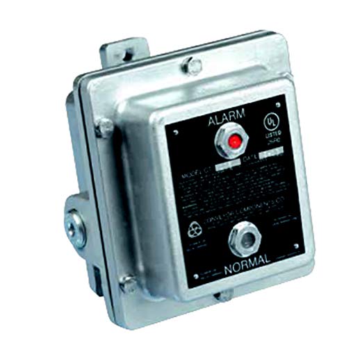
Figure 1: Front view of the Conveyor Components Model CT-105 Control Unit. The unit features a robust enclosure with visible "ALARM" (red LED) and "NORMAL" (green LED) indicators on the front panel.
Installation and Setup
Important Safety Information: Installation and maintenance of this equipment should only be performed by qualified and authorized personnel in accordance with all local and national electrical codes and safety regulations. Ensure power is disconnected before beginning any installation or wiring procedures.
Mounting
The CT-105 control unit is designed for secure mounting. Select a location that is stable, free from excessive vibration, and provides adequate access for wiring and observation of indicators. Use appropriate fasteners for the mounting surface.
Wiring
The unit requires a 120VAC input power supply. Connect the power supply to the designated terminals inside the enclosure. The DP/DT relay outputs are rated at 5 amps and should be wired to the control circuit or alarm system as required by the application. Ensure all connections are secure and properly insulated. Refer to the internal wiring diagram (if provided within the unit or separate documentation) for specific terminal assignments.
- Power Input: 120VAC.
- Relay Output: DP/DT, 5 amps.
- Tilt Probe Connection: Connect the intrinsically safe tilt probe(s) to the designated terminals.
Time Delay Adjustment (VR1)
The time delay potentiometer (VR1) allows adjustment of the alarm delay from 0.1 to 35 seconds. This feature helps prevent nuisance alarms from momentary tilt switch activations. Adjust VR1 using a small screwdriver to the desired delay setting. Clockwise rotation typically increases the delay.
Operation
Once properly installed and powered, the CT-105 control unit monitors the status of the connected tilt switch(es) and provides visual indication and relay output based on their state.
LED Indicators
- Green LED (NORMAL): Illuminates when the connected tilt switch(es) are in their normal, non-alarm state. This indicates that the monitored condition is within acceptable parameters.
- Red LED (ALARM): Illuminates when a connected tilt switch activates, indicating an alarm condition. The red LED will light up after the set time delay (VR1) has elapsed, confirming a sustained alarm state.
Relay Output
The DP/DT relay changes state when an alarm condition is detected and the time delay has elapsed. This relay can be used to activate external alarms, shut down machinery, or signal a control system. The relay will revert to its normal state when the tilt switch returns to its non-alarm position.
Maintenance
The CT-105 control unit is designed for minimal maintenance. However, periodic inspection is recommended to ensure optimal performance and longevity.
- Visual Inspection: Regularly inspect the enclosure for any signs of damage, corrosion, or loose connections. Ensure the NEMA 4X enclosure integrity is maintained.
- Cleaning: Keep the exterior of the unit clean. Use a soft, damp cloth to wipe away dust or debris. Do not use abrasive cleaners or solvents.
- Functionality Check: Periodically test the system by manually activating the tilt switch (if safely possible) to confirm the alarm LED illuminates and the relay activates as expected.
- Wiring Connections: Annually check all electrical connections for tightness and integrity.
Troubleshooting
This section provides guidance for common issues. For problems not listed here, contact technical support.
| Problem | Possible Cause | Solution |
|---|---|---|
| No LEDs illuminate. | No power to the unit; incorrect wiring; internal fuse blown. | Verify 120VAC power supply. Check wiring connections. Inspect and replace internal fuse if necessary (ensure power is off). |
| Alarm LED (Red) does not illuminate when tilt switch activates. | Faulty tilt switch; incorrect wiring of tilt switch; time delay (VR1) set too long; faulty internal relay. | Test the tilt switch independently. Check tilt switch wiring. Adjust VR1 to a shorter delay for testing. Contact support if relay is suspected faulty. |
| Normal LED (Green) does not illuminate when tilt switch is normal. | Faulty tilt switch; incorrect wiring of tilt switch; faulty internal relay. | Test the tilt switch independently. Check tilt switch wiring. Contact support if relay is suspected faulty. |
| Relay does not activate/deactivate. | Incorrect relay wiring; faulty relay; insufficient power to relay. | Verify relay output wiring. Check power supply to the relay circuit. Contact support if relay is suspected faulty. |
Specifications
| Attribute | Value |
|---|---|
| Model Number | CT-105 |
| Input Power | 120VAC |
| Relay Type | DP/DT |
| Relay Rating | 5 amps |
| LED Indicators | Normal (Green), Alarm (Red) |
| Enclosure Rating | NEMA 4X |
| Time Delay (VR1) | 0.1 to 35 Seconds |
| Compatible Probes | Intrinsically safe and cULus listed tilt probes |
| Manufacturer | Conveyor Components |
| Date First Available | May 30, 2019 |
| ASIN | B07SKC869M |
Warranty and Support
For information regarding product warranty, technical support, or service, please contact Conveyor Components Company directly. Refer to their official website or the original product packaging for contact details.
Manufacturer: Conveyor Components Company