1. Introduction
This manual provides essential information for the safe and correct installation, operation, and maintenance of the Generic Power Supply and Main Board, models TP.MT5581.PB761 and V400HJ9-D03. This board is designed as a replacement component for VIZIO D40f-G9 televisions. Please read these instructions thoroughly before proceeding with any installation.
2. Safety Information
Warning: Electrical components can be dangerous. Improper installation or handling may result in electric shock, fire, or damage to the television. Always follow these safety guidelines:
- Ensure the television is completely disconnected from the power source before beginning any work.
- Discharge any residual static electricity from your body before handling the board by touching a grounded metal object.
- Wear appropriate personal protective equipment, such as anti-static gloves.
- If you are not confident in your ability to perform this installation, seek assistance from a qualified technician.
- Do not attempt to repair or modify the board.
3. Installation
This section outlines the steps for replacing the power supply and main board in your VIZIO D40f-G9 television.
3.1. Board Overview
Familiarize yourself with the layout and key connection points of the replacement board.
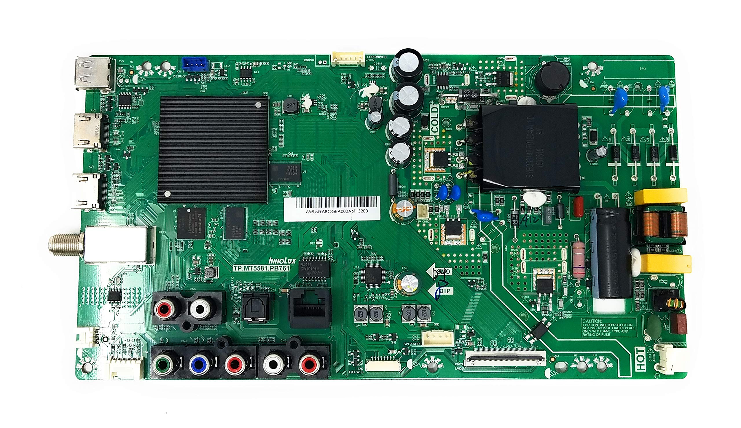
Figure 1: Generic Power Supply and Main Board TP.MT5581.PB761, V400HJ9-D03. This image displays the main board, highlighting key sections such as the power input, various audio/video ports, and internal components. Note the 'HOT' and 'COLD' sections for safety, as well as connectors for HDMI, USB, RJ45 (Ethernet), Optical Out, Line Out, Audio In, and CVBS In/YPbPr In.
3.2. Installation Steps
- Preparation: Ensure the television is unplugged from the wall outlet. Place the TV face down on a soft, clean surface to prevent screen damage.
- Remove Back Panel: Locate and remove all screws securing the TV's back panel. Carefully lift and remove the back panel.
- Locate Existing Board: Identify the existing power supply and main board assembly. It will be the large circuit board with numerous connections.
- Disconnect Cables: Carefully disconnect all cables connected to the existing board. This includes power cables, ribbon cables, and input/output cables (e.g., HDMI, USB, Ethernet, audio). Note the orientation and connection points for reassembly.
- Remove Old Board: Unscrew the mounting screws that secure the old board to the TV chassis. Carefully lift and remove the old board.
- Install New Board: Position the new TP.MT5581.PB761, V400HJ9-D03 board into place, aligning it with the screw holes. Secure it with the screws removed earlier. Do not overtighten.
- Reconnect Cables: Reconnect all cables to their corresponding ports on the new board. Ensure all connections are firm and correctly oriented. Refer to your notes or photos taken during disassembly if needed.
- Replace Back Panel: Carefully place the TV's back panel back into position and secure it with all screws.
4. Operation (Post-Installation Check)
After installation, perform the following checks to ensure proper functionality:
- Power On: Plug the television back into a power outlet. The TV should power on, and the standby indicator light should illuminate.
- Verify Display: Turn on the TV. A picture should appear on the screen.
- Test Inputs: Connect various devices (e.g., cable box, game console) to the HDMI, USB, and other input ports to confirm they are functioning correctly.
- Check Audio: Verify that sound is produced through the TV speakers or connected audio output.
5. Maintenance
The power supply and main board generally require no routine maintenance. To ensure longevity:
- Keep the television in a clean, dust-free environment.
- Avoid exposing the television to excessive moisture or extreme temperatures.
- Ensure adequate ventilation around the TV to prevent overheating.
6. Troubleshooting
If you encounter issues after installing the new board, consider the following:
- No Power: Double-check all power cable connections, both to the board and the wall outlet. Ensure the outlet is functional.
- No Picture/Sound: Verify that all ribbon cables and input/output cables are securely connected. Ensure the correct input source is selected on the TV.
- Intermittent Issues: Re-check all connections for looseness. Ensure no foreign objects are inside the TV.
- Still Experiencing Problems: If issues persist, it may indicate a problem with another component of the television or an incorrect installation. Re-verify all steps or consult a professional technician.
7. Specifications
| Brand | Generic |
| Model Numbers | TP.MT5581.PB761, V400HJ9-D03 |
| Compatible TV Model | VIZIO D40f-G9 |
| Item Weight | 1 Pound |
| Package Dimensions | 4 x 4 x 4 inches |
| Special Feature | Flat |
| Included Components | Power Supply and Main Board |
8. Warranty and Support
This product comes with a 30-day warranty from the date of purchase, covering manufacturing defects. This warranty does not cover damage caused by improper installation, misuse, accidents, or unauthorized modifications.
For technical support or warranty claims, please contact your retailer or the manufacturer directly. Please have your purchase receipt and product model numbers ready when contacting support.


