1. Introduction
This manual provides detailed instructions for the safe and effective operation of your LOMVUM T28C TRMS 6000 Counts Digital Multimeter. Please read this manual thoroughly before use and retain it for future reference.
The LOMVUM T28C is a True RMS digital multimeter designed for measuring AC/DC voltage, AC/DC current, resistance, capacitance, frequency, temperature, diode, and continuity. It also features Non-Contact Voltage (NCV) detection and transistor (hFE) testing, making it a versatile tool for electrical professionals and DIY enthusiasts.
2. Safety Information
WARNING: To avoid electric shock or personal injury, read and understand all safety information before using this product.
- Always ensure the multimeter is set to the correct function and range before making measurements.
- Do not exceed the maximum input values specified for each range. This device is rated CAT III 600V.
- Inspect test leads for damage before each use. Do not use if insulation is damaged or bare metal is exposed.
- Do not use the meter if it appears damaged or if the case is open.
- Exercise extreme caution when working with voltages above 30V AC RMS, 42V peak, or 60V DC. These voltages pose a shock hazard.
- Remove test leads from the circuit before changing functions.
- Replace batteries immediately when the low battery indicator appears to ensure accurate readings.
- Do not operate the meter in explosive gas, vapor, or dusty environments.
- Always disconnect power to the circuit and discharge all high-voltage capacitors before measuring resistance, continuity, diodes, or capacitance.
3. Package Contents
Verify that all items listed below are present and in good condition:
- 1 x LOMVUM T28C Digital Multimeter
- 1 x Pair of Test Leads (Red and Black)
- 4 x 1.5V AAA Batteries
- 1 x Temperature Probe
- 1 x User Manual (this document)

Image: The LOMVUM T28C Digital Multimeter displayed with its complete set of accessories, including the main unit, red and black test leads, four AAA batteries, and a temperature probe.
4. Product Overview
Familiarize yourself with the components and controls of your LOMVUM T28C Digital Multimeter.

Image: A detailed diagram of the LOMVUM T28C Digital Multimeter, clearly labeling its various components such as the LCD Backlit Screen, Non-contact Voltage Indicator, Rotary Switch, Function Select/Data Hold Button, Backlight/Flashlight Button, Range Button, and input receptacles (20A, mA, COM, VΩHzC/Live).
4.1 Key Components:
- LCD Backlit Screen: Displays measurement readings, units, and function indicators.
- Non-contact Voltage Indicator: Lights up and beeps when AC voltage is detected.
- Rotary Switch: Used to select the desired measurement function.
- FUNC/HOLD Button: Toggles between sub-functions (e.g., AC/DC, Diode/Continuity) and activates data hold.
- Backlight/Flashlight Button: Activates the screen backlight and the integrated LED flashlight.
- Range Button (Hz/Duty/Relative): For manual range selection or specific functions like frequency/duty cycle.
- Input Receptacles:
- COM: Common input for all measurements (black test lead).
- VΩHzC/Live: Input for voltage, resistance, frequency, capacitance, diode, continuity, and live wire detection (red test lead).
- mA: Input for milliampere current measurements (red test lead).
- 20A: Input for high current (up to 20A) measurements (red test lead).

Image: The LOMVUM T28C Digital Multimeter's display, highlighting its 3.0-inch backlit LCD screen and icons for AC/DC voltage, AC/DC current, frequency, resistance, temperature, duty cycle, capacitance, diodes, continuity, transistor (hFE), True RMS, and Non-Contact Voltage (NCV).
5. Setup
5.1 Battery Installation
- Ensure the multimeter is turned off and test leads are disconnected.
- Locate the battery compartment cover on the back of the meter.
- Use a screwdriver to open the battery compartment.
- Insert four 1.5V AAA batteries, observing the correct polarity (+/-).
- Replace the battery compartment cover and secure it with the screw.
5.2 Connecting Test Leads
- Insert the black test lead into the "COM" (Common) input jack.
- For most measurements (voltage, resistance, continuity, diode, capacitance, frequency, temperature), insert the red test lead into the "VΩHzC/Live" input jack.
- For current measurements, insert the red test lead into the "mA" jack (for milliamps) or the "20A" jack (for amperes), depending on the expected current.
6. Operating Instructions
This section details how to use the LOMVUM T28C for various electrical measurements.
6.1 General Operation
- Power On/Off: Rotate the central switch from "OFF" to any desired function to power on. Rotate back to "OFF" to power off. The meter features auto power-off after approximately 15 minutes of inactivity.
- Backlight/Flashlight: Press the * / 💡 button briefly to turn on/off the backlight. Press and hold the button to turn on/off the integrated LED flashlight.
- Data Hold: Press the FUNC/HOLD button briefly to freeze the current reading on the display. Press again to release.
- Function Selection: For functions with multiple modes (e.g., AC/DC voltage, Diode/Continuity), press the FUNC/HOLD button to cycle through the modes.

Image: The LOMVUM T28C Digital Multimeter's LED flashlight in use, providing illumination for measurements in a dimly lit electrical panel, enhancing safety and visibility.
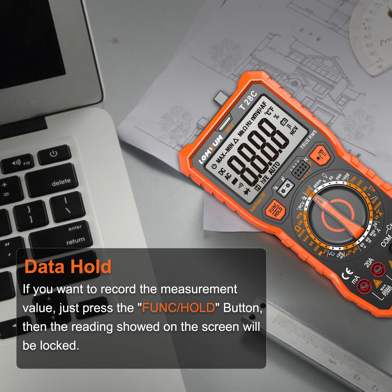
Image: The LOMVUM T28C Digital Multimeter showing a measurement value locked on its display, indicating the "Data Hold" function is active. This feature allows users to record readings conveniently.
6.2 Measuring AC/DC Voltage (V)
- Set the rotary switch to the V~ (AC Voltage) or V= (DC Voltage) position.
- Connect the black test lead to the "COM" jack and the red test lead to the "VΩHzC/Live" jack.
- Connect the test probes in parallel to the circuit or component being measured.
- Read the voltage value on the LCD screen.
6.3 Measuring AC/DC Current (A)
CAUTION: Never connect the test leads in parallel to a voltage source when measuring current, as this can blow the fuse or damage the meter.
- Set the rotary switch to the A~ (AC Current) or A= (DC Current) position, or the mA~ / mA= position.
- Connect the black test lead to the "COM" jack. Connect the red test lead to the "mA" jack for currents up to 600mA, or to the "20A" jack for currents up to 20A.
- Open the circuit where current is to be measured and connect the meter in series with the load.
- Read the current value on the LCD screen.
6.4 Measuring Resistance (Ω)
CAUTION: Ensure the circuit is de-energized and all capacitors are discharged before measuring resistance.
- Set the rotary switch to the Ω position.
- Connect the black test lead to "COM" and the red test lead to "VΩHzC/Live".
- Connect the test probes across the component to be measured.
- Read the resistance value on the LCD screen.
6.5 Continuity Test ()))
CAUTION: Ensure the circuit is de-energized before performing a continuity test.
- Set the rotary switch to the Ω position. Press FUNC/HOLD until the continuity symbol ())) appears.
- Connect the black test lead to "COM" and the red test lead to "VΩHzC/Live".
- Connect the test probes across the circuit or component.
- If the resistance is below approximately 50Ω, the meter will emit an audible beep, indicating continuity.
6.6 Diode Test (->|)
CAUTION: Ensure the circuit is de-energized before performing a diode test.
- Set the rotary switch to the Ω position. Press FUNC/HOLD until the diode symbol (->|) appears.
- Connect the black test lead to "COM" and the red test lead to "VΩHzC/Live".
- Connect the red probe to the anode and the black probe to the cathode of the diode. The display will show the forward voltage drop.
- Reverse the probes. The display should show "OL" (Open Loop) for a good diode.
6.7 Measuring Capacitance (F)
CAUTION: Ensure the capacitor is fully discharged before measuring capacitance to prevent damage to the meter.
- Set the rotary switch to the F (Capacitance) position.
- Connect the black test lead to "COM" and the red test lead to "VΩHzC/Live".
- Connect the test probes across the capacitor.
- Read the capacitance value on the LCD screen.
6.8 Measuring Frequency (Hz) / Duty Cycle (%)
- Set the rotary switch to the Hz position.
- Connect the black test lead to "COM" and the red test lead to "VΩHzC/Live".
- Connect the test probes in parallel to the signal source.
- Read the frequency value. Press the Hz/Duty/Relative button to switch to duty cycle measurement.
6.9 Measuring Temperature (°C/°F)
- Set the rotary switch to the °C/°F position.
- Connect the temperature probe to the "VΩHzC/Live" and "COM" jacks, observing polarity.
- Place the tip of the temperature probe on or near the object whose temperature is to be measured.
- Read the temperature value on the LCD screen. Press FUNC/HOLD to switch between Celsius and Fahrenheit.

Image: The LOMVUM T28C Digital Multimeter actively measuring the temperature of water using its included temperature probe, demonstrating its capability for thermal measurements.
6.10 Non-Contact Voltage (NCV) Detection
- Set the rotary switch to the NCV position.
- Move the top front part of the meter (NCV detection area) close to the conductor or outlet you want to test.
- If AC voltage is detected, the NCV indicator light will flash, and the meter will emit an audible beep, with the frequency of beeps increasing as the voltage strength increases.
6.11 Transistor (hFE) Test
- Set the rotary switch to the hFE position.
- Identify if the transistor is NPN or PNP.
- Insert the transistor's emitter, base, and collector leads into the corresponding holes in the hFE socket on the meter.
- Read the hFE value (DC current gain) on the LCD screen.

Image: The LOMVUM T28C Digital Multimeter showcasing its integrated kickstand for hands-free operation and a hanging magnet on the back, providing versatile placement options during measurements.
7. Maintenance
7.1 Cleaning
Wipe the meter's case with a damp cloth and mild detergent. Do not use abrasives or solvents. Ensure the meter is completely dry before use.
7.2 Battery Replacement
When the low battery indicator appears on the display, replace the batteries as described in Section 5.1. Always use four new 1.5V AAA batteries.
7.3 Fuse Replacement
WARNING: Fuse replacement should only be performed by qualified personnel. Incorrect fuse types can lead to damage or injury.
If the current measurement function fails, the fuse may need replacement. Refer to the specifications for the correct fuse type. To replace, open the back cover (similar to battery replacement) and carefully replace the blown fuse with a new one of the identical rating.
8. Troubleshooting
| Problem | Possible Cause | Solution |
|---|---|---|
| Meter does not power on. | Dead or incorrectly installed batteries. | Check battery polarity; replace batteries. |
| No reading or "OL" (Overload) displayed. | Incorrect range selected; open circuit; measurement exceeds range. | Select a higher range; check circuit connections; ensure measurement is within meter's capabilities. |
| Inaccurate readings. | Low battery; poor test lead connection; external interference. | Replace batteries; ensure secure connections; move away from strong electromagnetic fields. |
| Current measurement not working. | Blown fuse; incorrect input jack used. | Check and replace fuse if necessary; ensure red lead is in "mA" or "20A" jack. |
9. Specifications
| Feature | Detail |
|---|---|
| Display | 6000 Counts, 3.5/6-digit LCD with Backlight |
| True RMS | Yes |
| Safety Rating | IEC61010-1, CAT III 600V, Double Insulation |
| Power Source | 4 x 1.5V AAA Batteries (included) |
| AC/DC Voltage | Up to 600V |
| AC/DC Current | Up to 20A |
| Resistance | Up to 60MΩ |
| Capacitance | Up to 60mF |
| Frequency | Up to 10MHz |
| Temperature Range | -20°C ~ 1000°C / -4°F ~ 1832°F |
| Non-Contact Voltage (NCV) | Yes, with visual and audible alarm |
| Continuity Test | Yes, with audible alarm |
| Diode Test | Yes |
| Transistor (hFE) Test | Yes |
| Data Hold | Yes |
| Auto Power Off | Yes |
| Dimensions | 21.49 x 13.79 x 6.3 cm (approx. 7.67 x 3.54 x 2.48 inches) |
| Weight | 453.59 g (approx. 1 pound) |
10. Warranty and Support
Your LOMVUM T28C Digital Multimeter comes with a 24-Month Warranty from the date of purchase. Additionally, a Risk-Free Return within 30 Days policy is offered.
For technical support, warranty claims, or any questions regarding the operation of your device, please contact LOMVUM customer service through your original point of purchase or visit the official LOMVUM website for contact information.
Please retain your purchase receipt as proof of purchase for warranty purposes.