1. Introduction
This manual provides comprehensive instructions for the installation, operation, and maintenance of the KUS Mechanical Oil Pressure Sensor, model KE21104. This sensor is designed for reliable oil pressure measurement in various applications, including generators, vehicles, ships, and industrial process control systems.
The KE21104 sensor offers excellent anti-vibration performance, a long service life, and stable quality across a wide operating temperature range. Its robust design ensures dependable performance in demanding environments.
2. Product Overview
The KUS Mechanical Oil Pressure Sensor KE21104 is a precision instrument designed to monitor oil pressure. It features a standard NPT1/8 thread for easy installation and provides an output signal proportional to the measured pressure, along with an alarm function for critical pressure levels.

Figure 2.1: General view of the KUS Mechanical Oil Pressure Sensor KE21104. This image shows the overall design of the sensor, including its metallic body and electrical connection terminals.
3. Setup and Installation
3.1. Safety Precautions
- Ensure the power supply to the system is disconnected before installation to prevent electrical shock.
- Wear appropriate personal protective equipment (PPE), such as gloves and eye protection.
- Verify that the sensor's specifications match the system requirements before installation.
- Avoid overtightening the sensor during installation to prevent damage to the thread or sensor body.
3.2. Installation Steps
- Prepare the Mounting Location: Identify a suitable port on the engine or system for the oil pressure sensor. Ensure the port has an NPT1/8 thread.
- Apply Thread Sealant: Apply a suitable thread sealant (e.g., PTFE tape or liquid sealant) to the NPT1/8 thread of the sensor to ensure a leak-free seal.
- Install the Sensor: Carefully thread the sensor into the prepared port. Hand-tighten first, then use a wrench to tighten it securely, but do not overtighten.
- Connect Electrical Wiring:
- Connect the positive power supply (6-24V) to the appropriate terminal.
- Connect the output signal wire (10-184Ω) to your gauge or monitoring system.
- Connect the alarm wire (0.8Bar) to your alarm indicator or system.
- Ensure all connections are secure and properly insulated.
- Verify Installation: After installation, visually inspect all connections for tightness and proper wiring.
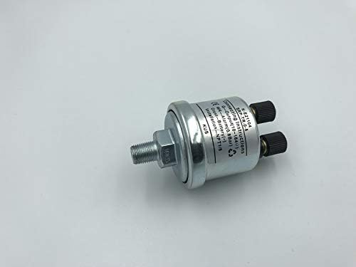
Figure 3.1: Side view of the sensor showing the NPT1/8 thread for installation. This image highlights the threaded connection point for secure mounting.

Figure 3.2: Close-up view of the electrical connection terminals on the sensor. This image details where the power, output, and alarm wires should be connected.
4. Operating Instructions
4.1. Basic Operation
Once properly installed and wired, the KUS KE21104 sensor will continuously monitor the oil pressure within its measuring range of 0 to 5 Bar. The sensor operates automatically when the system is powered on.
4.2. Reading Output and Alarm Function
- Pressure Reading: The sensor provides a standard resistance output signal ranging from 10 to 184 Ω, which corresponds to the 0-5 Bar pressure range. This signal is typically fed to a compatible oil pressure gauge or monitoring system for display.
- Alarm Function: The sensor is equipped with an alarm contact that activates when the oil pressure drops to 0.8 Bar or below. This alarm signal can be connected to an indicator light or audible alarm to alert the operator of low oil pressure conditions.
5. Maintenance
5.1. General Care and Inspection
- Periodically inspect the sensor and its connections for any signs of damage, corrosion, or leaks.
- Ensure electrical connections remain clean and secure.
- Clean the exterior of the sensor with a soft, dry cloth if necessary. Avoid using harsh chemicals or abrasive materials.
5.2. Storage
If the sensor needs to be stored, ensure it is kept in a clean, dry environment, away from extreme temperatures and direct sunlight. Protect the threaded portion and electrical terminals from physical damage.
6. Troubleshooting
This section addresses common issues that may arise during the use of the KUS Mechanical Oil Pressure Sensor KE21104.
| Problem | Possible Cause | Solution |
|---|---|---|
| No pressure reading or incorrect reading |
|
|
| Alarm constantly active or not activating |
|
|
| Oil leak around sensor |
|
|
7. Specifications
7.1. Technical Data
| Model Number | KE21104 |
| Operating Voltage | 6~24V |
| Measuring Range | 0~5 Bar |
| Alarm Pressure | 0.8 Bar |
| Output Signal | Standard resistance value: 10~184 Ω |
| Thread Fitting | NPT1/8 |
| Conducting Power | <5W |
| Operating Temperature | -25 ~ 120°C (120°C MAX 1H) |
| Protection Rank | IP66 |
| Material | Zinc |
| UPC | 603849021535 |
8. Warranty and Support
8.1. Warranty Information
KUS products are manufactured to high-quality standards and are typically covered by a manufacturer's warranty against defects in materials and workmanship. Please refer to the specific warranty terms provided at the time of purchase or contact KUS customer support for detailed warranty information.
8.2. Customer Support
For technical assistance, troubleshooting beyond this manual, or warranty claims, please contact KUS customer support. Have your product model number (KE21104) and purchase details ready when contacting support.
You can find contact information on the official KUS website or through your product retailer.


