
VOGURTIME DIY solder
VOGURTIME D2-5 Smart Car Kit Soldering Project Line Following Robot User Manual
Model: DIY solder | Brand: VOGURTIME
Introduction
The VOGURTIME D2-5 Smart Car Kit is an engaging and educational soldering project designed for hobbyists and learners interested in electronics, robotics, and automatic control. This kit allows you to build a line-following robot car that automatically navigates along a black runway. It's an excellent tool for practicing soldering skills and understanding fundamental electronic principles.
Important Note: This soldering project requires basic electronics knowledge. Familiarity with component identification and soldering techniques is highly recommended for successful assembly.

Components List
Before beginning assembly, please verify that all components listed below are present in your kit. Refer to the image for visual confirmation of the parts.
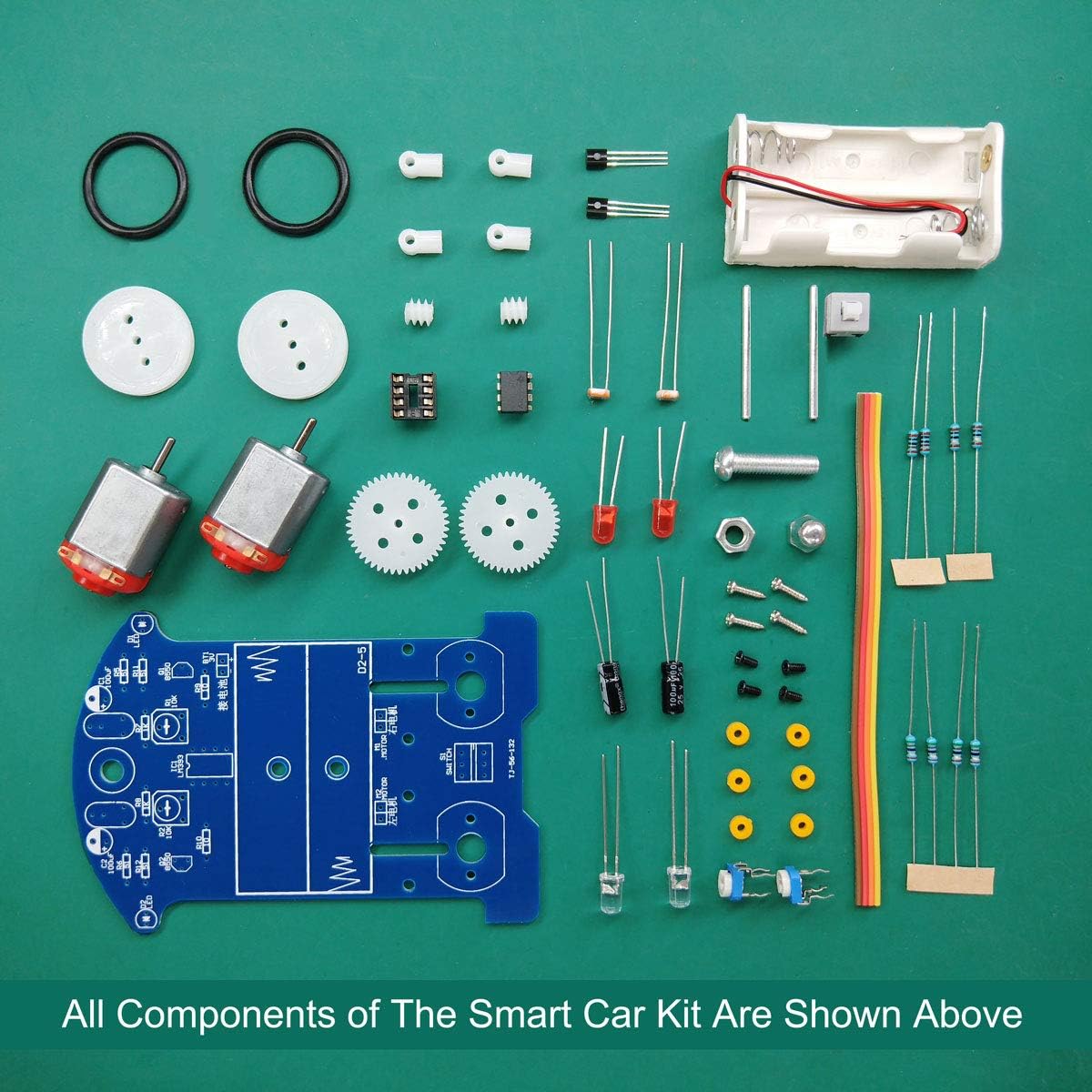
| Component | Description | Quantity (per kit) |
|---|---|---|
| Printed Circuit Board (PCB) | Main board for circuit assembly | 1 |
| Resistors | Various values (e.g., 10K, 1K, 51 ohm) | Assorted |
| Capacitors | Electrolytic capacitors (e.g., 100uF) | Assorted |
| IC Holder (8-pin) | For LM393 IC | 1 |
| LM393 IC | Comparator integrated circuit | 1 |
| Transistors | (e.g., 8550) | 2 |
| Potentiometers | Adjustable resistors for calibration | 2 |
| Photoresistors | Light-dependent resistors for line detection | 2 |
| LEDs (Red) | 5mm light-emitting diodes | 2 |
| LEDs (White) | For illumination/line sensing | 2 |
| Motors | DC motors for propulsion | 2 |
| Wheels | Plastic wheels with rubber tires | 2 |
| Gears | For motor-to-wheel connection | 2 |
| Steel Shafts | Axles for wheels | 2 |
| Three-way Sleeves | For shaft assembly | 2 |
| Battery Case | Holds 2x AA batteries (batteries not included) | 1 |
| Fasteners | Screws, nuts, gaskets | Assorted |
| Wires | For connections | Assorted |
Setup and Assembly
Follow these steps carefully to assemble your D2-5 Smart Car Kit. Pay close attention to component orientation and soldering quality.
1. Install Circuit Components
- Solder the resistors, 8-pin IC holder, switch, potentiometers, transistors, electrolytic capacitors, and the 5mm RED light-emitting diodes successively onto the circuit board. Follow the identifiers on the circuit diagram and the board for correct placement.
- Pay attention to the direction of the IC Socket. For easier debugging, do not install the LM393 IC yet.
- Install the photoresistors and white LEDs on the reverse side of the PCB. Ensure correct polarity and orientation.
- Install the battery case onto the designated area of the PCB.
- Perform an initial test of the circuit board before proceeding to mechanical assembly.


2. Install Mechanical Parts
- Install the four gaskets onto the circuit board. These will provide spacing for the mechanical components.
- Insert a steel shaft through the center hole of each wheel.
- Place a three-way sleeve onto the steel shaft, ensuring it is installed securely in place.
- Position a gear onto the steel shaft, in the center.
- Attach another three-axis sleeve to the end of the steel shaft.
- Finally, fit the two shafts on the steel shaft into the screw projections of the fixed washers.
- Install the motors onto the designated mounts on the PCB, ensuring the gears mesh correctly with the wheel gears.
3. Power On and Initial Test
Once all components are soldered and mechanical parts are assembled:
- Insert 2x AA batteries (not included) into the battery case, observing correct polarity.
- Power on the car using the switch.
- Carefully install the LM393 IC into its holder, ensuring correct orientation (notch alignment).
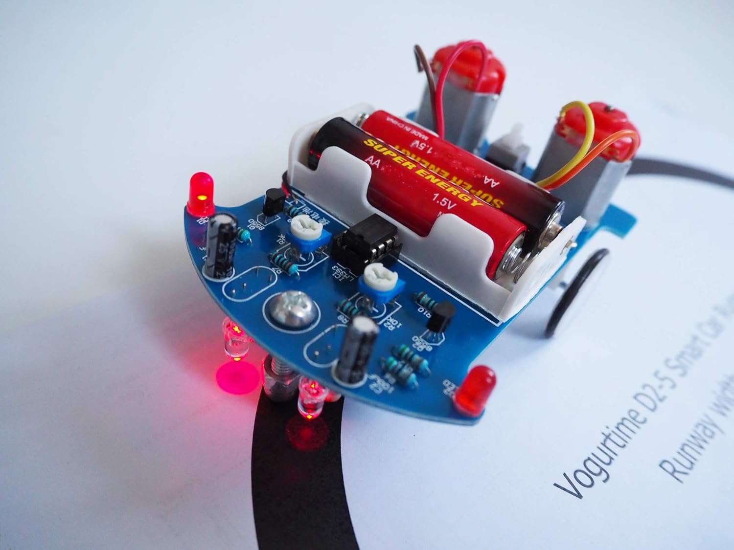
- Place the car on a test track (a black line on a white surface) to observe its line-following behavior.
Operating Instructions
The D2-5 Smart Car is designed to follow a black line on a white surface. The optimal black runway width is 16mm, but it can also track lines between 1.5cm and 2.0cm wide, created using black electrical tape or a black marker.
To operate the car:
- Prepare a track: Use the provided manual's track or create your own complex runway on a flat, light-colored surface.
- Place the car: Position the car on the black line.
- Activate: Turn on the power switch. The car should begin to follow the black line automatically.
The car uses its photoresistors and white LEDs to detect the contrast between the black line and the white surface, adjusting its motor speeds to stay on track. Ensure the environment has adequate lighting for optimal sensor performance.
Troubleshooting
If your D2-5 Smart Car is not functioning as expected, consider the following common issues and solutions:
- Car does not move:
- Check battery installation and ensure batteries are fresh (2x AA required).
- Verify all soldering joints are solid and free of cold joints or bridges.
- Ensure motors are correctly connected and gears are meshing properly.
- Confirm the power switch is in the 'ON' position.
- Car does not follow the line correctly:
- Adjust the potentiometers (trim pots) on the PCB. These control the sensitivity of the line-following sensors. Small adjustments can significantly impact performance.
- Check the orientation of the photoresistors and white LEDs. Incorrect polarity or placement can affect line detection.
- Ensure the black line is within the recommended width (1.5cm - 2.0cm) and has good contrast with the surface.
- Verify that the LM393 IC is correctly inserted into its socket with the notch aligned.
- One motor not working:
- Inspect soldering connections for that motor and its associated components (transistors, resistors).
- Check for any short circuits or broken traces on the PCB.
- Ensure the motor's wires are securely connected.
- Components overheating:
- Immediately disconnect power.
- Check for any short circuits on the PCB, especially around ICs and transistors.
- Verify correct component placement and polarity.
Specifications
| Attribute | Detail |
|---|---|
| Model Number | DIY solder |
| Working Voltage | 3V (2x AA batteries) |
| Finished Car Size | 104 x 72 x 55 mm (approx.) |
| Item Weight | 5.9 ounces (approx.) |
| Recommended Track Width | 16mm (or 1.5cm - 2.0cm black tape) |
| Skills Involved | Electronics, Soldering, Mechanical Assembly, Basic Robotics |
Maintenance
To ensure the longevity and optimal performance of your D2-5 Smart Car Kit, follow these maintenance guidelines:
- Cleaning: Gently wipe the car's surface with a dry, soft cloth to remove dust and debris. Avoid using liquids or harsh chemicals.
- Battery Replacement: Replace AA batteries when the car's performance degrades or it stops moving. Always use fresh batteries of the same type. Remove batteries if storing the car for extended periods to prevent leakage.
- Storage: Store the car in a cool, dry place away from direct sunlight and extreme temperatures.
- Component Inspection: Periodically check soldering joints for cracks or looseness. Ensure all mechanical connections (gears, shafts) are secure.
Warranty and Support
For any questions, concerns, or technical support regarding your VOGURTIME D2-5 Smart Car Kit, please contact VOGURTIME customer service. Refer to the product packaging or the retailer's website for specific contact information.
While this kit is designed for educational purposes and soldering practice, VOGURTIME is committed to providing assistance for any manufacturing defects or missing components. Please retain your proof of purchase for warranty claims.
Ask a question about this manual
Ask about setup, troubleshooting, compatibility, parts, safety, or missing instructions. Manuals+ will review the question and use this page’s manual context to help answer it.