
1. Introduction
The VOGURTIME D2-5 Smart Car Kit is an educational soldering project designed to introduce users to basic electronics, mechanical assembly, and the principles of line-following robotics. This kit allows you to build a small robot car that can automatically follow a black line on a white surface. It is an excellent tool for learning and practicing soldering skills and understanding fundamental electronic concepts.
2. Safety Information
Please read and understand all safety instructions before beginning assembly. This kit involves soldering, which uses high temperatures and can produce fumes. Adult supervision is recommended for younger users.
- Always work in a well-ventilated area to avoid inhaling solder fumes.
- Wear appropriate eye protection (safety glasses) to protect against splashes or flying debris.
- Soldering irons become extremely hot. Avoid direct contact with the tip and allow components to cool before handling.
- Use a stable soldering iron stand.
- Ensure proper disposal of electronic waste and used batteries.
- Do not short-circuit batteries.
3. Package Contents
Before starting assembly, verify that all components listed below are present in your kit. Refer to the image for a visual representation of the components.
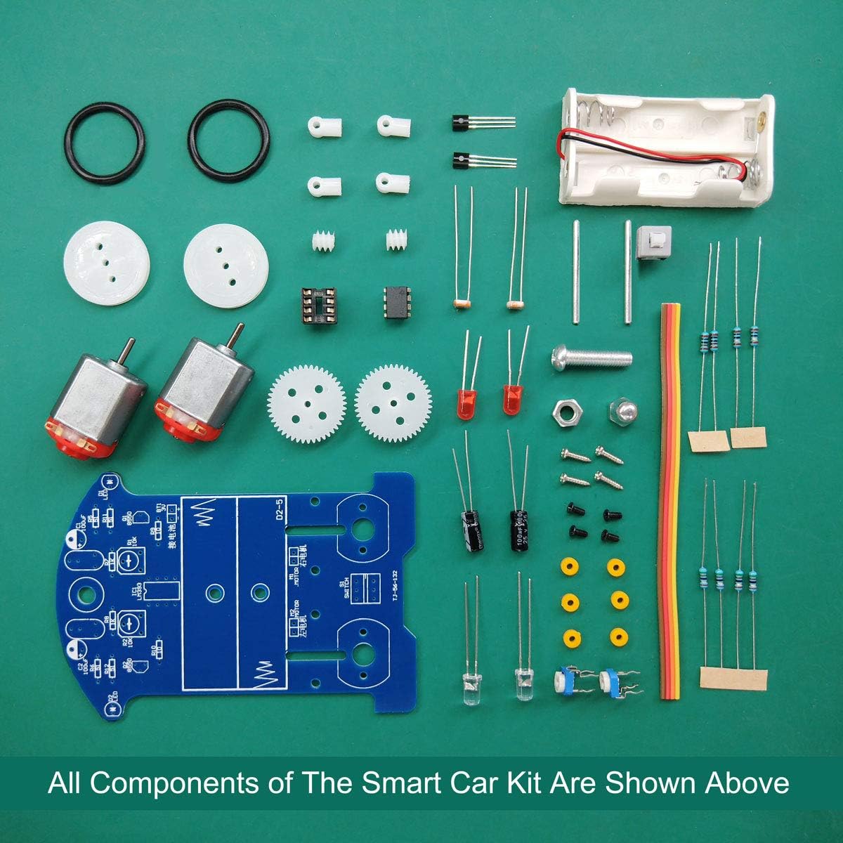
Figure 3.1: All components of the D2-5 Smart Car Kit. This includes the PCB, motors, wheels, battery holder, various resistors, capacitors, diodes, IC socket, IC chip, transistors, potentiometers, screws, and wires.
The kit typically includes:
- Printed Circuit Board (PCB)
- DC Motors (2)
- Wheels (2) and Rubber Tires (2)
- Battery Holder (for 2x AA batteries)
- LM393 IC Chip
- 8-pin IC Socket
- Photoresistors (2)
- White LEDs (2)
- Red LEDs (2)
- Transistors (2)
- Potentiometers (2)
- Various Resistors and Capacitors
- Power Switch
- Mechanical Fasteners (screws, nuts, spacers, shafts, gears)
- Connecting Wires
4. Setup and Assembly
This section guides you through the step-by-step assembly of your D2-5 Smart Car Kit. Basic soldering tools (soldering iron, solder, wire cutters, safety glasses) are required.
4.1. Circuit Installation (Soldering)
Carefully solder each component onto the Printed Circuit Board (PCB) according to the markings on the board and the circuit diagram. Pay close attention to component polarity and orientation where applicable.

Figure 4.1.1: Detailed view of key electronic components such as the LM393 IC, motors, and photoresistors, which are part of the kit.
- Solder Resistors, IC Holder, Switch, Potentiometers, Transistors, Electrolytic Capacitors, and Red LEDs: Solder these components onto the circuit board. Ensure the 8-pin IC holder is oriented correctly (notch aligns with PCB marking). Do not install the LM393 IC chip into its holder yet. This facilitates debugging.
- Install Photoresistors and White LEDs: Solder these components onto the reverse side of the PCB. Ensure they are positioned correctly to function as sensors.
- Install Battery Case: Solder the wires from the battery case to the designated pads on the PCB.
- Initial Circuit Test: Before proceeding, perform a basic continuity check or power test (without the LM393) to ensure no short circuits and basic power flow.

Figure 4.1.2: The circuit diagram illustrating the connections between sensor, comparator, motor, and power sections, alongside a partially assembled car.
4.2. Mechanical Parts Installation
Once the circuit board is fully soldered, proceed with assembling the mechanical components.
- Install Gaskets: Attach the four gaskets to the circuit board using the provided screws. These act as spacers.
- Assemble Wheels and Shafts:
- Insert a steel shaft through the center hole of each wheel.
- Place a three-way sleeve onto the steel shaft, securing it in place.
- Position a gear onto the steel shaft, ensuring it is centered.
- Place another three-axis sleeve onto the end of the steel shaft.
- Fit the two shafts into the screw projections of the fixed washers on the PCB.
- Install Motors: Securely attach the DC motors to the designated positions on the PCB, ensuring their shafts align with the gears. Solder the motor wires to the appropriate pads on the PCB.
4.3. Final Power-On and LM393 Installation
After all soldering and mechanical assembly are complete:
- Insert Batteries: Place two AA batteries (not included) into the battery holder, observing correct polarity.
- Power On: Flip the power switch to the ON position. The car should not move yet.
- Install LM393 IC: Carefully insert the LM393 IC chip into its 8-pin socket, ensuring the notch on the chip aligns with the notch on the socket and PCB.
- Test Functionality: The car is now ready for operation.
5. Operating Instructions
The D2-5 Smart Car is designed to follow a black line on a light-colored surface. Its photoresistors detect the contrast between the line and the background, guiding the motors to keep the car on track.
- Prepare a Track: Create a track using black electrical tape (1.5 to 2.0 cm wide) on a white or light-colored surface. The track can be straight, curved, or complex.
- Place the Car: Position the car so its front sensors are directly over the black line.
- Power On: Turn the power switch to the ON position. The car should begin to follow the black line.
- Adjust Potentiometers (Calibration): If the car struggles to follow the line, drifts off, or oscillates excessively, use a small screwdriver to gently adjust the two potentiometers on the PCB. These adjust the sensitivity of the photoresistors. Fine-tune them until the car tracks the line smoothly.
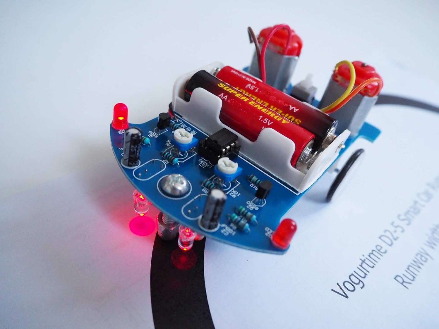
Figure 5.1: The D2-5 Smart Car Kit actively following a black line on a white surface, demonstrating its line-tracking capability.
6. Maintenance
To ensure the longevity and optimal performance of your D2-5 Smart Car Kit, follow these maintenance guidelines:
- Battery Replacement: When the car's performance degrades (e.g., slower movement, erratic line following), replace the two AA batteries with fresh ones. Always use good quality alkaline batteries.
- Cleaning: Keep the photoresistors and white LEDs clean and free of dust or debris, as this can affect their ability to detect the line. Use a soft, dry cloth.
- Storage: When not in use for extended periods, remove the batteries to prevent leakage and store the car in a dry, cool place.
- Inspecting Connections: Periodically check soldered connections for any signs of loosening or corrosion, especially if the car experiences rough handling.
7. Troubleshooting
If you encounter issues with your D2-5 Smart Car Kit, refer to the following troubleshooting tips:
| Problem | Possible Cause | Solution |
|---|---|---|
| Car does not power on. |
|
|
| Car does not move. |
|
|
| Car drifts off the line or moves erratically. |
|
|
| Solder pads lift off the PCB easily. |
|
|
8. Specifications
| Feature | Detail |
|---|---|
| Model | D2-5 Smart Car Kit |
| Brand | VOGURTIME |
| Working Voltage | 3V DC |
| Power Source | 2 x AA Batteries (not included) |
| Finished Car Size (L x W x H) | 104 x 72 x 55 mm |
| Material | Steel (components), PCB (fiberglass) |
| Educational Objective | Soldering skills, basic electronics, robotics |
9. Warranty and Support
VOGURTIME products are manufactured with quality in mind. This kit is intended for educational and hobbyist use. For specific warranty details or technical support, please contact VOGURTIME directly through their official channels or the retailer where the product was purchased. Please retain your proof of purchase for any warranty claims.