1. Introduction
This manual provides detailed instructions for the installation, operation, and application of the Taidacent LM331 Voltage to Frequency (V/F) and Frequency to Voltage (F/V) Converter Module. Please read this manual thoroughly before using the module to ensure proper functionality and safety.
2. Product Overview
The Taidacent LM331 module is a precision voltage-to-frequency and frequency-to-voltage converter. It is designed for applications requiring accurate conversion between analog voltage signals and digital frequency signals.
Key Features:
- Utilizes the LM331 precision V/F converter IC.
- Supports a wide supply voltage range: 4V to 40V.
- Compact size: 50mm x 33mm.
- Versatile applications including remote sensor monitoring and tachometer circuits.
3. Specifications
| Parameter | Value |
|---|---|
| Model | ZC-kangweiLM331 |
| IC | LM331 |
| Supply Voltage Range | 4V to 40V |
| Module Dimensions | 50mm x 33mm |
| Conversion Type | Voltage-to-Frequency (V/F), Frequency-to-Voltage (F/V) |
4. Setup and Connections
This section details the physical connections and initial setup for the LM331 module.
Module Layout and Pinout
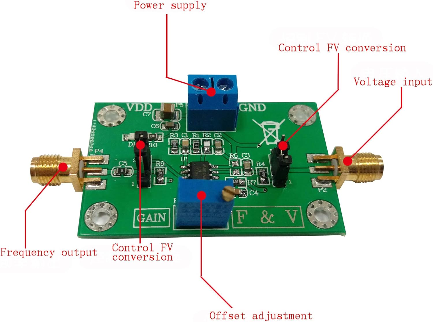
Figure 1: Taidacent LM331 module with key connection points and adjustment potentiometers labeled.
Refer to Figure 1 for the location of the following connection points and controls:
- Power Supply (VDD/GND): Connect your DC power source (4V to 40V) to these terminals. Ensure correct polarity.
- Voltage Input: This is the analog voltage signal input for Voltage-to-Frequency conversion.
- Frequency Output: This terminal provides the digital frequency signal output.
- Control FV Conversion: This pin or jumper setting determines whether the module operates in Voltage-to-Frequency or Frequency-to-Voltage mode. Consult the specific circuit diagram for detailed configuration.
- Offset Adjustment: A potentiometer for fine-tuning the output offset.
- Gain Adjustment: A potentiometer for adjusting the conversion gain.
Basic Wiring Diagram (Example for V/F Conversion)
For Voltage-to-Frequency conversion, connect your input voltage to the "Voltage input" terminal and observe the frequency output at the "Frequency output" terminal. Ensure the "Control FV Conversion" is set for V/F mode.
For Frequency-to-Voltage conversion, connect your input frequency to the "Frequency input" (often the same as "Frequency output" depending on configuration) and observe the voltage output at the "Voltage input" (often the same as "Voltage input" depending on configuration). Ensure the "Control FV Conversion" is set for F/V mode.
Note: Always ensure the power supply is within the specified range (4V-40V) to prevent damage to the module.
5. Operation
Voltage-to-Frequency (V/F) Conversion
In V/F mode, an input voltage is converted into a proportional output frequency.
- Connect the module as described in the Setup section for V/F conversion.
- Apply a stable DC voltage to the Voltage Input.
- Use an oscilloscope or frequency counter to measure the output frequency at the Frequency Output terminal.
- Adjust the Gain potentiometer to calibrate the desired voltage-to-frequency ratio.
- Adjust the Offset potentiometer to fine-tune the output frequency at zero input voltage, if necessary.

Figure 2: Module under test, showing a multimeter reading and a function generator output. This setup might be used for F/V conversion testing or as a frequency source for V/F output verification.
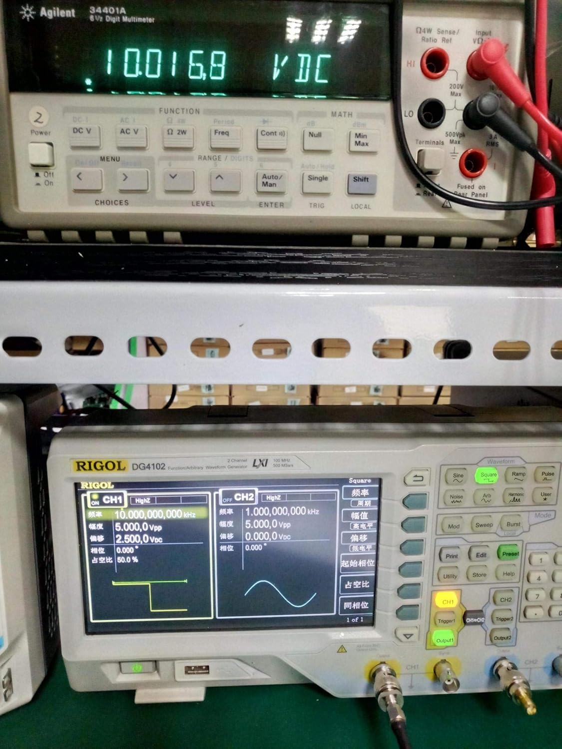
Figure 3: Another test scenario, showing a higher voltage reading on the multimeter, indicating a different conversion point or input.

Figure 4: Test setup with a lower voltage reading on the multimeter, demonstrating the module's response across a range of inputs.

Figure 5: Oscilloscope display showing the frequency output of the module, indicating a stable square wave at approximately 9.86 kHz.
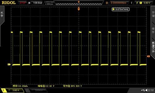
Figure 6: Oscilloscope trace showing a square wave output at 10.20 kHz, demonstrating the module's frequency generation capability.

Figure 7: Oscilloscope trace showing a square wave output at 7.88 kHz, illustrating the module's response to different input conditions.
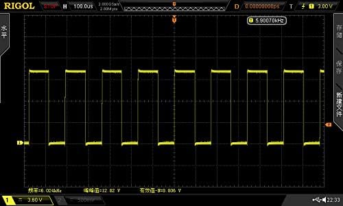
Figure 8: Oscilloscope trace showing a square wave output at 5.90 kHz, further demonstrating the module's operational range.
Frequency-to-Voltage (F/V) Conversion
In F/V mode, an input frequency is converted into a proportional output voltage.
- Connect the module as described in the Setup section for F/V conversion.
- Apply a stable frequency signal to the Frequency Input.
- Use a multimeter to measure the output voltage at the Voltage Input terminal.
- Adjust the Gain potentiometer to calibrate the desired frequency-to-voltage ratio.
- Adjust the Offset potentiometer to fine-tune the output voltage at zero input frequency, if necessary.
6. Applications
Typical Applications
- Remote Sensor Monitoring: Converting analog sensor outputs (e.g., temperature, pressure) into frequency signals for transmission over long distances with reduced noise susceptibility.
- Tachometer Circuits: Converting rotational speed (frequency) into a proportional voltage for display or control.
- Analog-to-Digital Conversion: As a front-end for microcontrollers to convert analog signals into a measurable frequency.
- Frequency Generation: Creating precise frequency signals from a voltage input.
7. Troubleshooting
No Output / Incorrect Output
- Power Supply: Verify that the power supply voltage is within the 4V-40V range and connected with correct polarity.
- Connections: Double-check all input and output connections for proper wiring.
- Mode Selection: Ensure the "Control FV Conversion" setting is correctly configured for the desired V/F or F/V mode.
- Potentiometer Settings: The Gain and Offset potentiometers can significantly affect output. Try adjusting them to see if the output changes. They might be set to an extreme value.
- Input Signal: Confirm that the input voltage or frequency signal is present and within the expected range for the module's operation.
Unstable Output
- Noise: Ensure the input signal and power supply are clean and free from excessive noise. Use shielded cables if necessary.
- Grounding: Verify proper grounding of the module and connected equipment.
8. Maintenance
The Taidacent LM331 module is designed for reliable operation and requires minimal maintenance.
- Cleaning: Keep the module clean and free from dust and debris. Use a soft, dry cloth for cleaning. Avoid using liquids or solvents.
- Storage: Store the module in a dry, static-free environment when not in use.
- Inspection: Periodically inspect connections for looseness or corrosion.
9. Warranty and Support
For warranty information or technical support regarding your Taidacent LM331 module, please refer to the seller's terms of service or contact Taidacent customer support directly through their official channels. Keep your purchase receipt for warranty claims.