1. Introduction
This manual provides detailed instructions for the installation, operation, and maintenance of the MAXWXKING SF-104 Digital Display Temperature Controller. This intelligent thermostat is designed for precise temperature regulation in cold storage and refrigerator environments, offering features such as temperature display, control, and defrost management.
Package Contents:
- 1 x Digital Display Thermostat (SF-104)
- 1 x Power Transformer (220V Input, 12V 160mA Output)
- 2 x Temperature Probes (NTC, 2 meters long)

Figure 1: The SF-104 Digital Display Temperature Controller, accompanied by its power transformer and temperature probes, as included in the package.
2. Setup and Installation
Proper installation is crucial for the optimal performance of the SF-104 controller. Ensure all connections are secure and follow the wiring diagram carefully.
Dimensions and Mounting:
- Overall Dimensions: 77mm (length) x 35mm (width) x 60mm (depth)
- Hole Size for Mounting: 71mm x 29mm
Wiring Instructions:
The controller requires connection to a 12V AC power source (supplied by the included transformer), two NTC temperature probes, and outputs for compressor, defrost heater, and evaporator fan. Refer to the diagram below for terminal connections.

Figure 2: Detailed wiring diagram for the SF-104 controller, showing connections for power, sensors, compressor, defrost heater, and evaporator fan.
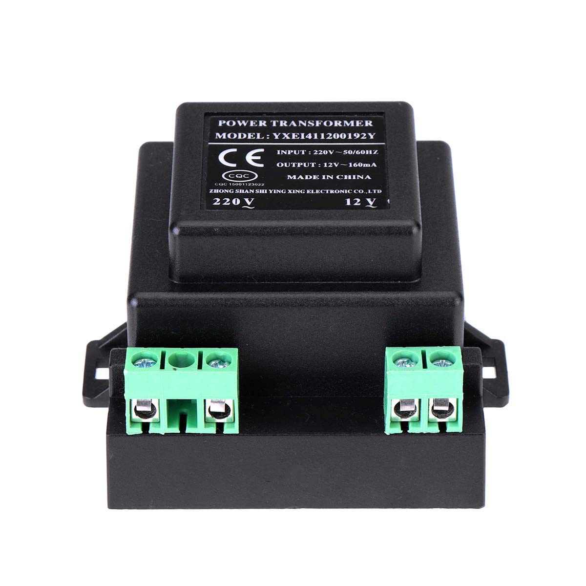
Figure 3: The external sealed power transformer, which converts 220V AC to 12V AC for the controller's operation.

Figure 4: The two NTC temperature probes, each 2 meters long, used for measuring storage temperature and controlling defrost cycles.
3. Operating Instructions
The SF-104 controller features a digital display and intuitive buttons for setting and monitoring temperatures.

Figure 5: Front panel of the SF-104 controller, showing the digital display and control buttons.
Key Functions:
- Temperature Display: Shows the current measured temperature. Display range: -45°C to 66°C (-45°F to 150°F).
- Temperature Control: Regulates the temperature within the set range. Control range: -45°C to 45°C (-45°F to 120°F). Default setting is 0°C (32°F).
- Defrost Control: Supports manual and automatic defrosting via a heater. Defrost can be terminated by time or temperature.
- Evaporator Fan Control: Manages the operation of the evaporator fan.
- Set Memory: Retains programmed settings even after power loss.
- Parameter Lock: Prevents accidental changes to settings.
- Self-Diagnosis: Built-in diagnostic capabilities to identify potential issues.
- Celsius/Fahrenheit Selection: Allows switching between temperature units.
Setting Parameters:
Use the 'SET' button to enter parameter setting mode. Navigate through parameters using the up/down arrows and confirm changes with 'SET'. Refer to the full product manual (if available from manufacturer) for a complete list of parameters and their functions.
4. Maintenance
The SF-104 controller is designed for durability. Regular maintenance is minimal but important for longevity.
General Care:
- Keep the unit clean and free from dust and debris. Use a soft, dry cloth for cleaning.
- Ensure the operating environment adheres to the specified conditions:
- Working Environment Temperature: -10°C to 60°C (14°F to 140°F)
- Relative Humidity: 20% to 90% (non-condensing)
- Periodically check all wiring connections for tightness and signs of wear.
5. Troubleshooting
This section addresses common issues you might encounter with the SF-104 controller.
Common Issues and Solutions:
- Incorrect Temperature Reading: Check if the temperature probes are correctly installed and not damaged. Ensure they are placed in the appropriate sensing locations.
- Controller Not Powering On: Verify the power transformer is correctly connected and receiving 220V input. Check the 12V AC output from the transformer to the controller.
- Compressor/Defrost/Fan Not Activating: Check the relay contact capacity specifications to ensure the connected load does not exceed the controller's limits. For loads exceeding direct connection capacity (e.g., >1KW for defrost heater, or large compressors), an external AC contactor must be used.
- Parameter Lock Engaged: If settings cannot be changed, the parameter lock feature may be active. Refer to the operating instructions to unlock parameters.
- Restoring Factory Defaults: If unexpected behavior occurs, the unit can be reset to factory defaults via a button operation (refer to specific button sequence in the full manual).
- Self-Diagnosis Errors: The controller has self-diagnosis capabilities. If an error code is displayed, consult the manufacturer's documentation for specific error code meanings.
6. Specifications
| Parameter | Value |
|---|---|
| Model | SF-104 (Digital Thermostat, Frozen) |
| Measuring Temperature Display Range | -45°C to 66°C (-45°F to 150°F) |
| Measurement Accuracy | ±1°C (±2°F) |
| Control Temperature Range | -45°C to 45°C (-45°F to 120°F) |
| Overall Dimensions (L x W x D) | 77mm x 35mm x 60mm |
| Hole Size for Mounting | 71mm x 29mm |
| Working Environment Temperature | -10°C to 60°C (14°F to 140°F) |
| Relative Humidity | 20% to 90% (no condensation) |
| Power Transformer Input | 220V~50/60Hz |
| Power Transformer Output | AC 12V~160mA |
| Temperature Probe Type | NTC, 2 probes (storage temperature, defrost control) |
| Temperature Probe Length | 2 meters |
| Compressor Relay Contact Capacity | Normally open 20A/250VAC (for 1P or less compressors, larger require AC contactor) |
| Defrost Heating Wire Relay Contact Capacity | Normally open 10A/250VAC (for 1KW load, larger require AC contactor) |
| Evaporator Fan Relay Contact Capacity | Normally open 5A/250VAC |
| Item Weight | 1 Pound |
| Controller Type | Push Button |
| Special Feature | Temperature Display |
| Color | White |
7. Warranty and Support
For warranty information and technical support, please refer to the documentation provided with your purchase or contact the seller directly. Keep your proof of purchase for any warranty claims.