1. Introduction
This manual provides essential information for the proper installation, operation, and maintenance of your GOOFIT 22mm CNC Hydraulic Clutch Brake Master Cylinder Lever. This universal component is designed for various motorcycles, pocket dirt bikes, ATVs, and scooters with 22mm (7/8 inch) handlebars and 125cc-250cc engines. Please read this manual thoroughly before installation and use to ensure safe and optimal performance.
2. Safety Information
- Professional Installation Recommended: Installation of brake and clutch systems requires specialized knowledge and tools. If you are not confident in your mechanical abilities, seek assistance from a qualified motorcycle technician.
- Brake Fluid: Use only DOT-approved brake fluid as specified by your vehicle manufacturer. Avoid mixing different types of brake fluid. Brake fluid is corrosive; avoid contact with paintwork and skin.
- Bleeding the System: After installation, the hydraulic system must be properly bled to remove all air bubbles. Failure to do so will result in brake failure.
- Regular Inspection: Periodically inspect the brake and clutch system for leaks, wear, and proper function. Ensure all fasteners are securely tightened.
- Handlebar Diameter: This product is designed for 22mm (7/8 inch) handlebars. Ensure compatibility with your vehicle before installation.
3. Package Contents
Verify that all items are present and undamaged upon opening the package:
- 1x GOOFIT 22mm CNC Hydraulic Clutch Master Cylinder Lever Assembly
- 1x GOOFIT 22mm CNC Hydraulic Brake Master Cylinder Lever Assembly
- Hydraulic line(s) (quantity and length may vary by kit)
- Mounting hardware (bolts, washers)
- Keys for brake lock (if applicable)

Figure 3.1: Complete GOOFIT Hydraulic Clutch and Brake Lever Kit.
4. Specifications
| Mounting Hole Diameter | 22 mm (approximately 7/8 inch) |
| Material | High-quality metal (aircraft-grade aluminum) |
| Brake Fluid Compatibility | DOT-approved brake fluid (check vehicle manual) |
| Master Cylinder Piston | Large master cylinder piston for effective hydraulic pressure |
| Brake Light Switch | Integrated electric switch for brake light activation |
| Banjo Bolt Size | Standard M8 size |
| Adjustability | 6-position adjustable levers for personalized reach |

Figure 4.1: Side view of the lever, showing approximate length.

Figure 4.2: Side view of the slave cylinder, showing approximate length.
5. Setup and Installation
Follow these general steps for installation. Specific procedures may vary based on your vehicle model. Always refer to your vehicle's service manual for detailed instructions.
5.1. Preparation
- Ensure the vehicle is stable on a stand.
- Gather necessary tools (wrenches, screwdrivers, brake fluid, bleeding kit).
- Wear appropriate safety gear, including gloves and eye protection.
5.2. Removing Existing Levers (if applicable)
- Carefully disconnect any electrical connections to the existing brake/clutch levers.
- Loosen the mounting bolts that secure the old master cylinder and lever assembly to the handlebar.
- Disconnect the hydraulic line(s) from the old master cylinder. Be prepared for brake fluid to leak; use a drain pan.
- Remove the old assembly.
5.3. Installing New GOOFIT Levers
- Position the new GOOFIT master cylinder lever assembly on the 22mm (7/8 inch) handlebar. Ensure proper orientation and comfortable reach.
- Secure the assembly using the provided mounting bolts. Do not overtighten initially.
- Connect the hydraulic line(s) to the new master cylinder using the M8 banjo bolt. Ensure crush washers are correctly placed to prevent leaks.
- Reconnect any electrical wires for the brake light switch.

Figure 5.1: Example of GOOFIT lever installed on a motorcycle.
5.4. Filling and Bleeding the Hydraulic System
This is a critical step for hydraulic systems. Improper bleeding can lead to brake failure.
- Fill the master cylinder reservoir with the recommended DOT brake fluid.
- Locate the bleed nipple on the caliper or slave cylinder. Attach a clear hose to the nipple and place the other end into a container with some brake fluid.
- Pump the lever several times until pressure builds. Hold the lever in.
- While holding the lever, open the bleed nipple briefly to release air and fluid. Close the nipple before releasing the lever.
- Repeat steps 3 and 4 until no air bubbles are visible in the fluid exiting the hose.
- Maintain the fluid level in the master cylinder reservoir throughout the bleeding process.
5.5. Installation Videos
Video 5.1: Installation of a Clutch Brake Pump Lever Assembly. This video demonstrates the process of installing a hydraulic clutch/brake lever, including connecting the hydraulic line and initial bleeding steps.
Video 5.2: Motorcycle Brake Installation. This video provides a general guide on installing motorcycle brakes, which can be helpful for understanding the hydraulic system setup.
6. Operating Instructions
6.1. Lever Adjustment
The GOOFIT levers feature a 6-position adjustment mechanism to customize the lever reach to your hand size and preference. To adjust, locate the adjustment dial or screw near the pivot point of the lever and rotate it to select the desired position. Test the feel and ensure full engagement and disengagement of the brake/clutch.
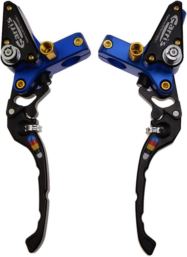
Figure 6.1: Close-up of the lever adjustment mechanism.
6.2. Brake Light Activation
The integrated electric switch activates your vehicle's brake light when the lever is pulled. Ensure this connection is properly made during installation for safety.
6.3. Operation Videos
Video 6.1: Hydraulic Brake Lever Adjustment. This short video demonstrates the adjustment feature of a hydraulic brake lever.
Video 6.2: Motorcycle Clutch and Brake Levers Adjustment. This short video illustrates the adjustment of both clutch and brake levers.
7. Maintenance
- Brake Fluid Level: Regularly check the brake fluid level in the reservoir. Refill with the correct DOT fluid if low.
- Fluid Condition: Inspect the brake fluid for discoloration or contamination. Replace fluid according to your vehicle manufacturer's recommendations or if it appears dirty.
- Lever Pivot Points: Keep the lever pivot points clean and lightly lubricated to ensure smooth operation.
- General Cleaning: Clean the levers and master cylinder assemblies with a mild soap and water solution. Avoid harsh chemicals that may damage the finish or seals.
8. Troubleshooting
- Spongy Lever Feel: This usually indicates air in the hydraulic system. Re-bleed the system thoroughly.
- Loss of Braking/Clutch Power: Check brake fluid level. Inspect for leaks in the hydraulic lines or connections. Re-bleed the system. If the issue persists, inspect the master cylinder and caliper/slave cylinder for internal wear or damage.
- Lever Not Returning Fully: Check for obstructions, proper lubrication of the pivot, or a faulty return spring. Ensure the adjustment mechanism is not set too tight.
- Brake Light Not Activating: Verify the electrical connections to the brake light switch. Check the switch for proper function.
9. Warranty and Support
GOOFIT is committed to customer satisfaction. If you encounter any issues or are not satisfied with your order, please contact us for replacement or refund. Our customer support team is available to assist you with product-related inquiries.
For further assistance, please visit the GOOFIT Store on Amazon.


