1. Introduction
The Thsinde 18Z-III is a 20000-count, 4 1/2 digit automatic digital multimeter designed for high precision, stable performance, and reliability. This battery-driven instrument features a 21mm high LCD display for clear readings and includes a peak value retention function. It is capable of measuring DC/AC voltage, DC/AC current, resistance, capacitance, diode, temperature, continuity, electric field induction (NCV), and frequency. Utilizing a double integral A/D conversion core, the 18Z-III is an ideal tool for laboratories, factories, and electronics enthusiasts.
2. Safety Information
To ensure safe operation and avoid damage to the meter, please observe the following safety precautions:
- Always use the correct function and range for measurements.
- Do not exceed the maximum input values specified for each range.
- Inspect test leads for damage before each use. Do not use if insulation is compromised.
- Ensure the meter is switched off before connecting or disconnecting test leads to a circuit.
- Exercise extreme caution when working with live circuits. Avoid contact with bare wires or terminals.
- Do not operate the meter if it appears damaged or if the battery cover is not properly closed.
- Replace the battery promptly when the low battery indicator appears to ensure accurate readings.
- Adhere to local and national safety codes.
3. Package Contents
Verify that all items are present in the package:
- Thsinde 18Z-III Digital Multimeter
- 9V Battery (pre-installed or included separately)
- Test Leads (1 pair)
- Alligator Clips (2 pieces)
- English User's Manual (this document)
4. Product Features
- Display: 20000 Counts, 4 1/2 digit LCD with LED backlight.
- Measurement Functions: DC/AC Voltage, DC/AC Current, Resistance, Capacitance, Diode, Temperature, Continuity, NCV (Non-Contact Voltage), Frequency, Duty Cycle.
- True RMS Measurement: Provides accurate readings for non-sinusoidal waveforms.
- Auto-Ranging: Automatically selects the appropriate measurement range.
- Data Hold: Freezes the displayed reading.
- Peak Hold: Captures and displays the maximum peak value.
- Low Battery Indication: Alerts when battery replacement is needed.
- Auto Power Off: Conserves battery life by automatically shutting down after a period of inactivity.
- Overload Protection: Protects the meter from damage due to excessive input.
- High Pressure Alarm: Provides an alert under certain high voltage conditions.

Figure 1: Overview of Thsinde 18Z-III Multimeter's capabilities and display features.
5. Product Overview
Familiarize yourself with the components and controls of your Thsinde 18Z-III Digital Multimeter.
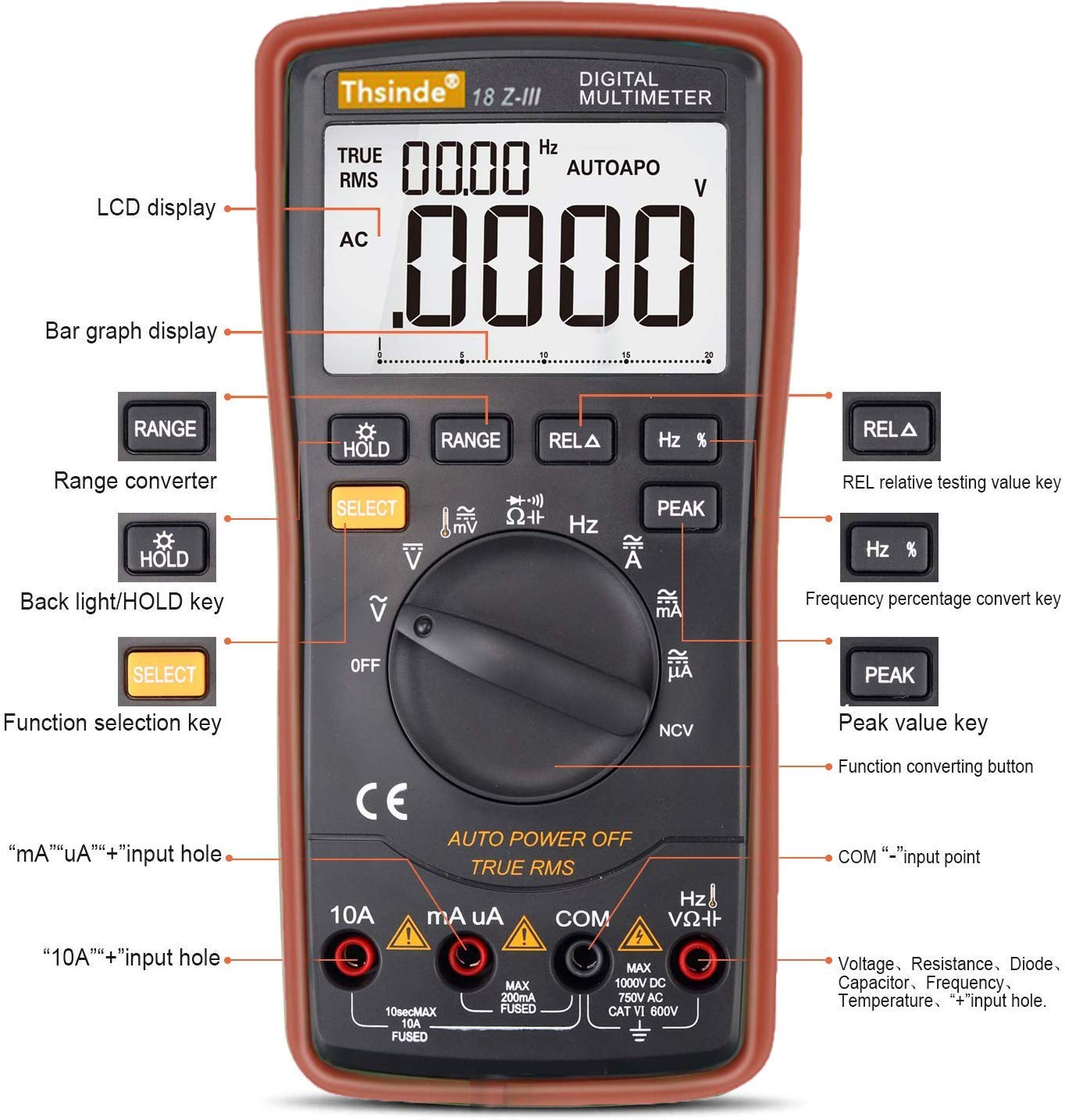
Figure 2: Front panel layout and controls of the Thsinde 18Z-III Digital Multimeter.
- LCD Display: Shows measurement readings, units, and function indicators.
- Bar Graph Display: Provides an analog representation of the measured value.
- RANGE Button: Manually selects measurement range (disables auto-ranging).
- HOLD / Backlight Button: Short press to activate Data Hold; long press to toggle backlight.
- SELECT Button: Toggles between different measurement modes within a single rotary switch position (e.g., AC/DC, Diode/Continuity).
- REL A Button: Activates relative measurement mode.
- Hz % Button: Toggles between frequency and duty cycle measurement.
- PEAK Button: Activates peak hold function.
- Rotary Function Switch: Selects the primary measurement function (OFF, V, mV, A, mA, uA, Ohm, Capacitance, Diode/Continuity, NCV, Temperature, Frequency).
- Input Jacks:
- 10A Input: For measuring currents up to 10A.
- mA uA Input: For measuring milliampere and microampere currents.
- COM Input: Common (negative) terminal for all measurements.
- VΩHz Input: Positive terminal for Voltage, Resistance, Capacitance, Frequency, Diode, and Temperature measurements.
6. Setup
6.1 Battery Installation
The Thsinde 18Z-III Multimeter operates on a single 9V battery, which is included. The battery compartment is located on the back of the unit.
- Ensure the multimeter is turned OFF.
- Locate the screw on the battery compartment cover on the back of the meter.
- Use a screwdriver to loosen the screw and remove the battery cover.
- Connect the 9V battery to the battery clips, observing correct polarity (+ and -).
- Place the battery into the compartment and replace the cover, securing it with the screw.
6.2 Connecting Test Leads
Always connect the black test lead to the COM jack. Connect the red test lead to the appropriate input jack based on the measurement type:
- For Voltage, Resistance, Capacitance, Frequency, Diode, and Temperature measurements: Connect the red test lead to the VΩHz jack.
- For mA/uA Current measurements: Connect the red test lead to the mA uA jack.
- For 10A Current measurements: Connect the red test lead to the 10A jack.
Ensure test leads are fully inserted into the jacks.
7. Operating Instructions
Turn the rotary function switch to the desired measurement function. The meter will automatically select the appropriate range unless the RANGE button is pressed.
7.1 DC/AC Voltage Measurement (V, mV)
- Connect the black test lead to COM and the red test lead to VΩHz.
- Turn the rotary switch to V (for volts) or mV (for millivolts).
- Press SELECT to toggle between DC and AC voltage if necessary.
- Connect the test probes across the circuit or component to be measured.
7.2 DC/AC Current Measurement (A, mA, uA)
CAUTION: Never connect the meter in parallel with a voltage source when measuring current. This can blow the fuse or damage the meter.
- Connect the black test lead to COM.
- For currents up to 200mA, connect the red test lead to mA uA. For currents up to 10A, connect the red test lead to 10A.
- Turn the rotary switch to the appropriate current range (A, mA, or uA).
- Press SELECT to toggle between DC and AC current if necessary.
- Open the circuit and connect the test probes in series with the circuit to be measured.
7.3 Resistance Measurement (Ω)
CAUTION: Ensure the circuit is de-energized and all capacitors are discharged before measuring resistance.
- Connect the black test lead to COM and the red test lead to VΩHz.
- Turn the rotary switch to Ω.
- Connect the test probes across the component to be measured.
7.4 Capacitance Measurement (F)
CAUTION: Ensure capacitors are fully discharged before measurement to prevent damage to the meter.
- Connect the black test lead to COM and the red test lead to VΩHz.
- Turn the rotary switch to Capacitance symbol.
- Connect the test probes across the capacitor.
7.5 Diode Test and Continuity
- Connect the black test lead to COM and the red test lead to VΩHz.
- Turn the rotary switch to the Diode/Continuity symbol.
- Press SELECT to toggle between Diode Test and Continuity Test.
- For Diode Test: Connect the red probe to the anode and the black probe to the cathode. The display shows the forward voltage drop. Reverse the probes; the display should show OL (Open Loop).
- For Continuity Test: Connect the probes across the circuit. A continuous beep indicates continuity (low resistance).
7.6 Non-Contact Voltage (NCV) Detection
- Turn the rotary switch to NCV.
- Move the top front part of the meter close to the conductor being tested.
- The meter will beep and the NCV indicator will light up if AC voltage is detected. The intensity of the beeping and light indicates the strength of the electric field.
7.7 Temperature Measurement
- Connect the black test lead to COM and the red test lead to VΩHz.
- Turn the rotary switch to Temperature symbol (usually °C/°F).
- Insert the temperature probe (thermocouple, if included) into the VΩHz and COM jacks, observing polarity.
- Place the tip of the temperature probe on or near the object whose temperature is to be measured.
- Press SELECT to switch between Celsius (°C) and Fahrenheit (°F).

Figure 3: Thsinde 18Z-III Multimeter performing a temperature measurement.
7.8 Frequency and Duty Cycle Measurement (Hz, %)
- Connect the black test lead to COM and the red test lead to VΩHz.
- Turn the rotary switch to Hz.
- Connect the test probes across the signal source.
- Press Hz % to toggle between frequency (Hz) and duty cycle (%).
7.9 Data Hold (HOLD)
Press the HOLD button briefly to freeze the current reading on the display. Press it again to release the hold function.
7.10 Peak Hold (PEAK)
Press the PEAK button to capture and display the maximum peak value of a measurement. Press it again to exit peak hold mode.
7.11 Backlight
Press and hold the HOLD button for approximately 2 seconds to turn the LCD backlight on or off. The backlight will automatically turn off after about 15 seconds to conserve battery.
7.12 Auto Power Off
The meter will automatically power off after approximately 15 minutes of inactivity to save battery life. To disable this feature, hold down the SELECT button while turning the rotary switch from OFF to any function. To re-enable, simply power off and on normally.
8. Specifications
| Parameter | Specification |
|---|---|
| Display | 19999/20000 Counts, 4 1/2 Digit LCD |
| DC Voltage | 200mV/2V/20V/200V/1000V |
| AC Voltage | 200mV/2V/20V/200V/750V |
| DC Current | 200uA/2000uA/20mA/200mA/10A |
| AC Current | 200uA/2000uA/20mA/200mA/10A |
| Resistance | 200Ω/2kΩ/20kΩ/200kΩ/2MΩ/20MΩ |
| Capacitance | 20nF/200nF/2uF/20uF/200uF/2000uF |
| Temperature | -20°C to 1000°C / -4°F to 1832°F |
| Frequency | 10Hz-20MHz |
| Duty Cycle | 0.1%-99% |
| Power Source | 9V Battery (included) |
| Working Environment | 0°C to 40°C, relative humidity <75% |
| Item Weight | 454 g |
| Dimensions | 22.5 x 16.5 x 6 cm |
| Material | ABS |
9. Maintenance
9.1 Battery Replacement
When the low battery indicator appears on the display, replace the 9V battery immediately to ensure accurate measurements. Follow the steps in Section 6.1 for battery installation.
9.2 Cleaning
Wipe the meter's casing with a damp cloth and a mild detergent. Do not use abrasives or solvents. Ensure the meter is completely dry before use.
9.3 Fuse Replacement
If the current measurement function fails, the fuse may need replacement. This meter uses HRC fuses. Refer to a qualified technician for fuse replacement to ensure proper type and rating are used.
10. Troubleshooting
| Problem | Possible Cause | Solution |
|---|---|---|
| No display or dim display | Low battery; Meter off; Poor battery connection. | Replace battery; Turn rotary switch to a function; Check battery connection. |
| "OL" (Overload) displayed | Input value exceeds selected range; Open circuit (for resistance/continuity). | Switch to a higher range (if not auto-ranging); Check circuit connection. |
| Inaccurate readings | Low battery; Incorrect function/range selected; Damaged test leads. | Replace battery; Select correct function/range; Inspect and replace test leads if damaged. |
| Current measurement not working | Blown fuse; Incorrect input jack used. | Replace fuse (refer to 9.3); Ensure red lead is in 10A or mA uA jack. |
| No continuity beep | Open circuit; Meter not in continuity mode. | Check circuit for breaks; Press SELECT to ensure continuity mode is active. |
11. Warranty and Support
For warranty information or technical support, please refer to the documentation provided at the time of purchase or contact Thsinde customer service directly. Keep your purchase receipt as proof of purchase.
For further assistance, you may visit the manufacturer's website or contact their support channels.