1. Introduction
This manual provides detailed instructions for the installation, operation, and maintenance of the Commercial Electric EXLEDRG120277 LED Exit Sign. This unit is designed for commercial applications, offering a reliable, energy-efficient life safety solution with a switchable red or green LED display and battery backup.
Please read these instructions thoroughly before installation and retain this manual for future reference.
2. Safety Information
- WARNING: Risk of electric shock. Disconnect power before installation or servicing.
- Installation and servicing should be performed by qualified personnel only.
- Ensure the power source voltage (120V or 277V) matches the unit's requirements.
- Do not mount near gas or electric heaters.
- Ensure all connections are secure and properly insulated.
- The battery is a Ni-Cad 4.8-Volt type. Do not attempt to replace with other battery types.
- This product meets UL 924 life safety requirements and Title 20 requirements.
3. Package Contents
Verify that all components are present and undamaged before proceeding with installation.
- One (1) Commercial Electric LED Exit Sign (Model: EXLEDRG120277)
- One (1) 4.8V Ni-Cad Backup Battery
- Mounting Hardware (brackets, screws, wire nuts)
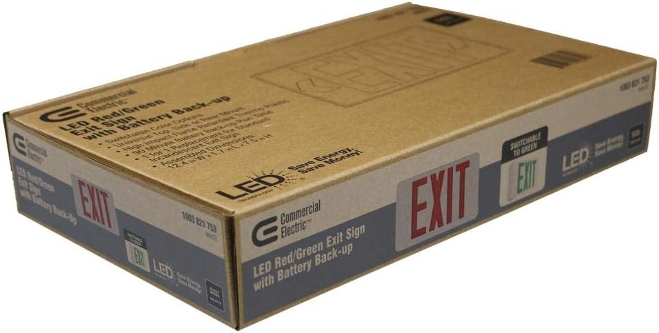
Image: The product packaging, indicating the LED Red/Green Exit Sign with Battery Back-up and switchable color options.
4. Specifications
| Model Number | EXLEDRG120277 |
| Input Voltage | 120-277 Volts AC |
| Battery Type | 4.8-Volt Ni-Cad (Nickel-Cadmium) |
| Emergency Run Time | 90 minutes |
| Light Source | Integrated LED |
| Display Color | Switchable Red or Green |
| Housing Material | High-impact flame-retardant thermoplastic (Acrylonitrile Butadiene Styrene) |
| Mounting Options | Wall, Top, or End Mount |
| Dimensions (L x W x H) | Approximately 12.2 x 8.3 x 7.44 inches (Product) |
| Weight | 2.78 pounds |
| Certifications | UL 924, Title 20 |
5. Setup and Installation
Before beginning installation, ensure power is disconnected at the circuit breaker. Follow all local and national electrical codes.
5.1 Mounting Options
The exit sign can be mounted in three configurations: wall, top, or end mount. Select the appropriate mounting method for your application.
- Wall Mount: Attach the unit directly to a wall surface.
- Top Mount: Use the provided canopy and mounting plate to suspend the unit from a ceiling.
- End Mount: Use the provided canopy and mounting plate to attach the unit to the side of a junction box.
5.2 Wiring Instructions
- Disconnect Power: Ensure the main power supply to the circuit is OFF.
- Open Housing: Carefully open the exit sign housing to access the internal wiring compartment.
- Connect AC Power:
- Connect the BLACK wire from the exit sign to the 120V AC HOT wire.
- Connect the RED wire from the exit sign to the 277V AC HOT wire. (Use only one of these hot connections based on your supply voltage. Insulate the unused hot wire.)
- Connect the WHITE wire from the exit sign to the COMMON/NEUTRAL wire.
- Connect the GREEN wire from the exit sign to the GROUND wire.
- Connect Battery: Plug the 4.8V Ni-Cad battery pack connector into the designated receptacle on the circuit board. Ensure a secure connection.
- Close Housing: Carefully close the exit sign housing, ensuring no wires are pinched.
5.3 Red/Green Color Selection
This unit features a switchable LED display, allowing you to select either red or green illumination for the "EXIT" text. A small switch or jumper is located inside the unit, typically near the wiring compartment. Consult the internal labels for the exact location and method to switch between red and green display modes.

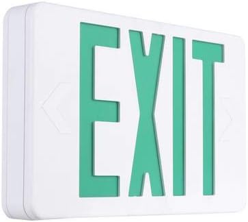
Image: The exit sign illuminated in red (left) and green (right), demonstrating the switchable color feature.
6. Operating Instructions
6.1 Initial Operation and Battery Charging
After installation and connecting the battery, restore AC power to the unit. The exit sign will illuminate, and the battery will begin charging. Allow the battery to charge for a minimum of 24 hours before performing any tests to ensure full capacity.
6.2 Normal Operation
Under normal AC power conditions, the LED exit sign will remain illuminated. The internal battery charger will maintain the Ni-Cad battery at full charge.
6.3 Emergency Operation (Battery Backup)
In the event of an AC power failure, the unit will automatically switch to battery backup mode, illuminating the exit sign for a minimum of 90 minutes. When AC power is restored, the unit will revert to normal operation and begin recharging the battery.
6.4 Testing the Unit
Regular testing is crucial to ensure the unit functions correctly during an emergency.
- Monthly Test: Press and hold the "TEST" button (usually a small push-button on the side or bottom of the unit) for approximately 5 seconds. The exit sign should illuminate from battery power. Release the button; the sign should return to AC power.
- Annual Test: Disconnect AC power to the unit for a full 90 minutes. The exit sign should remain illuminated for the entire duration. Reconnect AC power after the test.

Image: An installed Commercial Electric LED Exit Sign, demonstrating its typical application in a commercial environment.
7. Maintenance
- Cleaning: Clean the exterior of the unit with a soft, damp cloth. Do not use abrasive cleaners or solvents.
- Battery Replacement: The Ni-Cad battery has a typical lifespan of 5-7 years. If the unit fails to meet the 90-minute emergency run time during testing, the battery may need replacement. Contact a qualified electrician for battery replacement. Use only a 4.8V Ni-Cad replacement battery.
- Regular Inspection: Periodically inspect the unit for any visible damage, loose connections, or signs of wear.
8. Troubleshooting
| Problem | Possible Cause | Solution |
|---|---|---|
| Exit sign does not illuminate (AC power present). | No AC power to the unit; incorrect wiring; faulty LED. | Check circuit breaker. Verify wiring connections (120V/277V, neutral, ground). Contact qualified personnel if LED is faulty. |
| Exit sign does not illuminate during power outage (battery backup fails). | Battery not connected; battery not charged; battery faulty/old. | Ensure battery is securely plugged in. Allow 24 hours for initial charge. Replace battery if old or faulty. |
| Exit sign does not stay illuminated for 90 minutes during annual test. | Battery not fully charged; battery capacity degraded. | Ensure battery has charged for 24 hours. Replace battery if it fails to hold charge. |
| Incorrect display color (Red/Green). | Color selection switch/jumper set incorrectly. | Refer to Section 5.3 and adjust the internal color selection switch/jumper. |
9. Warranty and Support
This Commercial Electric LED Exit Sign (Model: EXLEDRG120277) is covered by a 5-year warranty from the date of purchase. This warranty covers defects in materials and workmanship under normal use.
For warranty claims, technical support, or replacement parts, please contact Commercial Electric customer service. Keep your proof of purchase for warranty validation.
Note: The Ni-Cad battery is typically covered by a separate, shorter warranty period, often 1 year. Refer to specific battery documentation if available.