
1. Introduction
This manual provides essential information for the setup, operation, and maintenance of your DollaTek ESP32 Wireless Stick Development Board. Please read this manual thoroughly before using the device to ensure proper functionality and to prevent damage.
2. Product Overview
The DollaTek ESP32 Wireless Stick is a versatile development board featuring an ESP32 chip, integrated WiFi, Bluetooth, and LoRa wireless communication capabilities. It includes a 0.49-inch OLED display and is designed for rapid prototyping and development, compatible with Arduino programming environments.

Figure 1: DollaTek ESP32 Wireless Stick Development Board. This image shows the compact design of the development board with its integrated OLED screen and pin headers.
Key Features:
- Processor: Lexin's ESP32 chip, 32-bit dual-core, 240MHz frequency.
- Wireless Connectivity: Integrated WiFi (802.11n, up to 150Mbps), Bluetooth v4.2 (BR/EDR and BLE), LoRa (SX1276 chip, 433MHz - 470MHz band).
- Display: 0.49-inch OLED screen.
- Power: Input via USB or lithium battery. Output: +5V (USB powered), +3.3V. Integrated lithium battery charging circuit.
- Interfaces: UART, SPI, I2C, I2S, Micro SD card, 12-bit ADC, 8-bit DAC, 29 general GPIO ports.
- Storage: 64M-Bits FLASH.

Figure 2: DollaTek ESP32 Wireless Stick with dimensions. This image illustrates the physical dimensions of the board, showing a length of 60mm, width of 23mm, and height of 8mm.

Figure 3: DollaTek ESP32 Wireless Stick highlighting wireless protocols. This image emphasizes the board's support for WiFi, BLE 4.2, and LoRa wireless communication functions, along with key performance metrics like WiFi speed (150Mbps), output power (+20 dBm), and receiving sensitivity (-128 dBm).
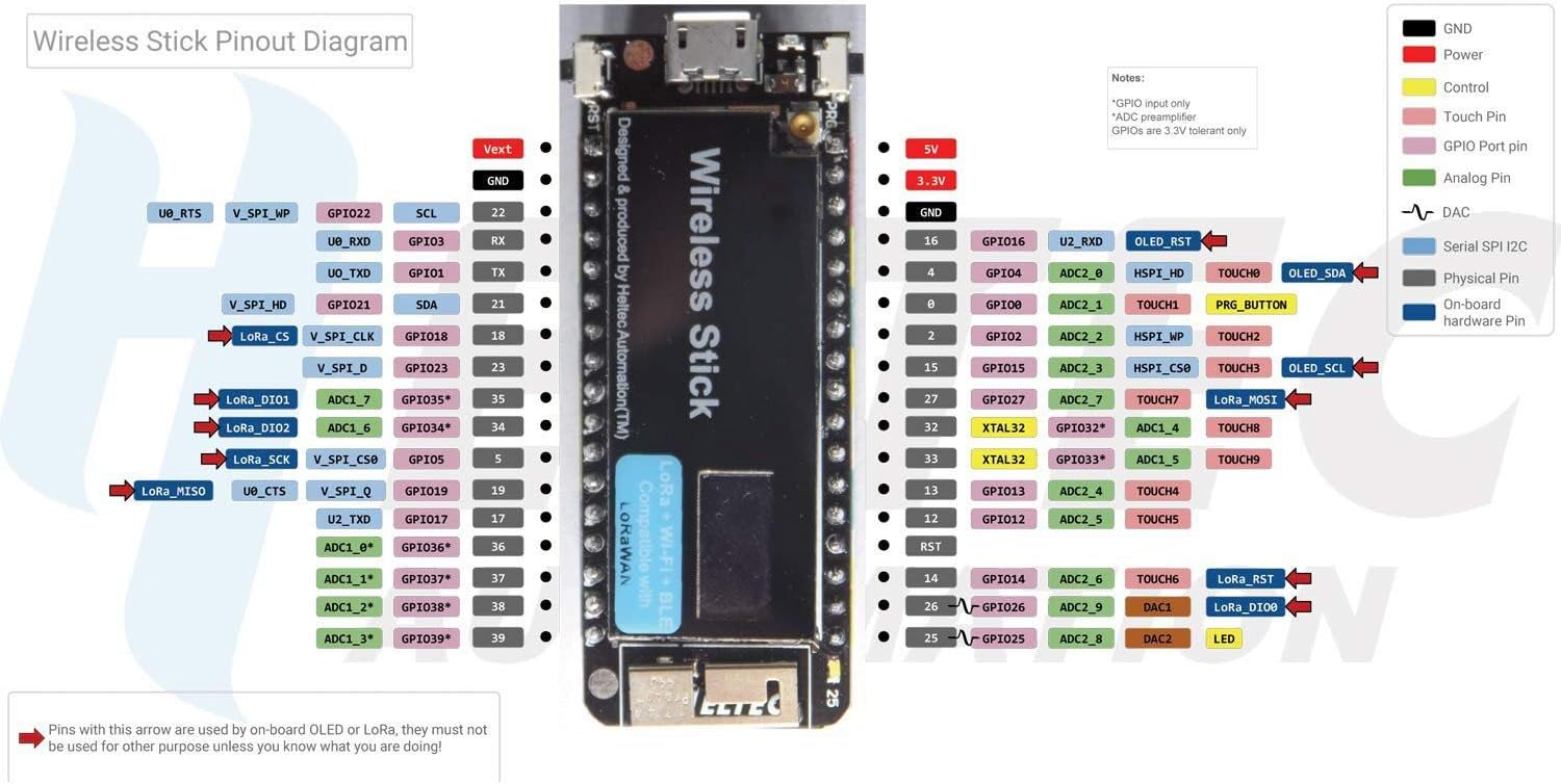
Figure 4: DollaTek ESP32 Wireless Stick Pinout Diagram. This detailed diagram provides a comprehensive mapping of all GPIO pins, power pins, and special function pins on the development board, essential for wiring and programming.
3. Setup
3.1 Package Contents
Verify that your package contains the following:
- 1 x DollaTek ESP32 Wireless Stick SX1276 Development Board (pins may not be soldered, pin stickers included).
3.2 Connecting the Board
- Prepare Pins: If the pin headers are not pre-soldered, carefully solder them to the board. Refer to the pinout diagram (Figure 4) for correct orientation.
- Power Supply: Connect the board to your computer using a Micro USB cable. The board can also be powered by a 3.7V lithium battery connected to the dedicated battery connector. The integrated circuit will manage charging when USB power is present.
- Initial Connection: Once connected via USB, the board should be recognized by your computer. Install necessary USB drivers if prompted by your operating system.
3.3 Development Environment Setup (Arduino IDE)
- Install Arduino IDE: Download and install the latest version of the Arduino IDE from the official Arduino website (www.arduino.cc/en/software).
- Add ESP32 Board Support:
- Open Arduino IDE, go to File > Preferences.
- In the 'Additional Boards Manager URLs' field, add:
https://raw.githubusercontent.com/espressif/arduino-esp32/gh-pages/package_esp32_index.json - Go to Tools > Board > Boards Manager.... Search for 'ESP32' and install the 'esp32 by Espressif Systems' package.
- Select Board: After installation, go to Tools > Board > ESP32 Arduino and select the appropriate board model (e.g., 'ESP32 Dev Module' or 'Wireless Stick' if available).
- Select Port: Go to Tools > Port and select the serial port corresponding to your connected ESP32 board.
4. Operating Instructions
4.1 Basic Programming
The DollaTek ESP32 Wireless Stick is compatible with the Arduino programming environment, allowing you to use standard Arduino libraries and C++ for development. You can upload sketches (programs) to the board via the USB connection.
4.2 Using the OLED Display
The integrated 0.49-inch OLED display can be controlled via I2C communication. Libraries such as the Adafruit SSD1306 library are commonly used with ESP32 boards for displaying text and graphics. Ensure you initialize the display with the correct I2C address and pin assignments (SDA, SCL) as per the pinout diagram.
4.3 WiFi and Bluetooth (BLE) Communication
The ESP32 chip provides robust WiFi and Bluetooth capabilities. You can use the standard ESP32 WiFi and Bluetooth libraries in the Arduino IDE to:
- Connect to existing WiFi networks (Station mode).
- Create an Access Point (AP mode).
- Establish Bluetooth Low Energy (BLE) connections for data exchange with other BLE devices.
- Utilize classic Bluetooth (BR/EDR) for various applications.
4.4 LoRa Communication
The SX1276 LoRa module enables long-range, low-power wireless communication. Specific LoRa libraries (e.g., RadioHead, LoRa by Sandeep Mistry) are available for Arduino to facilitate sending and receiving data packets. Ensure your LoRa frequency settings (433MHz - 470MHz) match the region and other LoRa devices you intend to communicate with.
4.5 GPIO Usage
The board offers 29 general-purpose input/output (GPIO) pins. These pins can be configured as digital inputs/outputs, analog inputs (ADC), analog outputs (DAC), or for specific peripheral functions (UART, SPI, I2C). Refer to the pinout diagram (Figure 4) for detailed pin assignments and capabilities.
5. Maintenance
5.1 Handling Precautions
- Avoid exposing the board to extreme temperatures, humidity, or direct sunlight.
- Handle the board by its edges to prevent electrostatic discharge (ESD) damage to components.
- Do not apply excessive force when connecting cables or components.
- Ensure power is disconnected before making any physical changes or connections to the board.
5.2 Storage
When not in use, store the development board in an anti-static bag or container in a cool, dry environment to protect it from dust and static electricity.
6. Troubleshooting
6.1 Board Not Detected by Computer
- Check USB Cable: Ensure the USB cable is functional and properly connected to both the board and the computer. Try a different USB cable.
- USB Drivers: Verify that the necessary USB-to-Serial drivers (e.g., CP210x or CH340, depending on the board's specific chip) are installed on your computer.
- Port Selection: In the Arduino IDE, ensure the correct serial port is selected under Tools > Port.
6.2 Sketch Upload Fails
- Board Selection: Confirm that the correct ESP32 board model is selected under Tools > Board > ESP32 Arduino.
- Boot Mode: Some ESP32 boards require holding down the 'BOOT' or 'FLASH' button while pressing and releasing the 'RESET' button to enter programming mode. Release the 'BOOT' button after the upload starts.
- Serial Monitor: Close any open Serial Monitor windows in the Arduino IDE before attempting to upload, as it can interfere with the upload process.
- Power Supply: Ensure the board is receiving sufficient power.
6.3 OLED Display Not Working
- Wiring: Double-check the I2C connections (SDA, SCL) to ensure they are correctly wired to the board's pins.
- I2C Address: Verify the I2C address used in your code matches the display's address (commonly 0x3C or 0x3D).
- Library: Ensure you are using a compatible OLED display library and that it is correctly initialized.
7. Specifications
| Feature | Specification |
|---|---|
| Processor | ESP32 (32-bit dual-core) |
| CPU Frequency | 240MHz |
| WiFi Standard | 802.11n (2.4GHz), up to 150Mbps |
| Bluetooth Standard | v4.2 (BR/EDR and BLE) |
| LoRa Chip | Semtech SX1276 |
| LoRa Frequency | 433MHz - 470MHz (optional) |
| OLED Display | 0.49 inch |
| Flash Memory | 64M-Bits (8MB) |
| Input Power | USB, Lithium Battery |
| Output Power | +5V (USB powered), +3.3V |
| Interfaces | UART, SPI, I2C, I2S, Micro SD card |
| ADC | 12-bit |
| DAC | 8-bit |
| GPIO Ports | 29 |
| Sleep Current | 800uA |
| Dimensions | Approx. 60mm x 23mm x 8mm |
| Weight | Approx. 1.41 ounces (40g) |
8. Warranty Information
For detailed warranty information, please refer to the official DollaTek website or contact your point of purchase. Keep your proof of purchase for warranty claims.
9. Support
For technical support, additional resources, or frequently asked questions, please visit the DollaTek official website or community forums. Online resources often provide example code, tutorials, and community assistance for ESP32 development boards.


