1. Introduction
This manual provides detailed instructions for the safe and effective use of the Sperry Instruments DM6410 8 Function Digital Multimeter. This device is designed for measuring AC/DC voltage, AC/DC current, resistance, continuity, diode, and battery testing (1.5V, 9V). It features a large LCD display, data hold function, and is built to industry standards for durability and safety.
2. Safety Information
WARNING: To avoid electric shock or personal injury, read and understand all instructions before using this multimeter. Always adhere to local and national safety codes.
- Do not apply more than the rated voltage, as marked on the meter, between the terminals or between any terminal and earth ground.
- Use caution when working with voltages above 30V AC RMS, 42V peak, or 60V DC. These voltages pose a shock hazard.
- Always disconnect the test leads from the circuit before changing functions or ranges.
- Ensure the test leads are in good condition, free from cracks or damaged insulation.
- Do not operate the meter if it appears damaged or if the case is open.
- This meter is rated CAT III 600V. Adhere to these safety categories for appropriate measurement environments.
- Replace the battery as soon as the low battery indicator appears to ensure accurate readings.
3. Product Overview
The Sperry Instruments DM6410 Digital Multimeter is a compact and robust tool for electrical measurements. Below are the key components and their functions.

Figure 3.1: Front view of the DM6410 Multimeter with key features labeled, including the 2000-count LCD screen, SELECT and HOLD buttons, rotary switch, and input jacks. It highlights compliance with ETL listed to UL and CSA standards and CAT III 600V design.
- LCD Display: Large 2000-count digital display for clear readings.
- Rotary Switch: Used to select the desired measurement function and range.
- SELECT Button: Toggles between AC/DC functions or other sub-functions within a range.
- HOLD Button: Freezes the current reading on the display.
- Input Jacks: Terminals for connecting test leads (A, COM, mA µA VΩ).

Figure 3.2: The DM6410 Digital Multimeter shown alongside its red and black test leads, which are essential for making electrical measurements.
4. Setup
4.1 Battery Installation
The DM6410 multimeter requires two AAA batteries for operation. The unit includes an auto-off function to conserve battery life.
- Ensure the multimeter is turned OFF.
- Locate the battery compartment on the back of the meter.
- Use a screwdriver to remove the screw securing the battery cover.
- Insert two AAA batteries, observing the correct polarity (+ and -).
- Replace the battery cover and secure it with the screw.
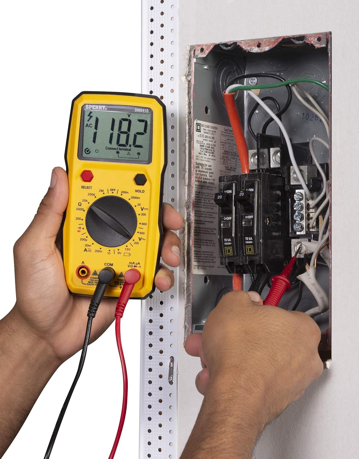
Figure 4.1: The rear of the DM6410 Multimeter, displaying the battery compartment cover and safety warnings. The compartment requires two 1.5V AAA batteries.
4.2 Test Lead Connection
Proper connection of test leads is crucial for accurate and safe measurements.
- Insert the black test lead into the 'COM' (common) input jack.
- For most voltage, resistance, continuity, and diode measurements, insert the red test lead into the 'VΩ' input jack.
- For current measurements (Amps), insert the red test lead into the 'A' or 'mA µA' input jack, depending on the expected current range.

Figure 4.2: The DM6410 Multimeter with the black test lead connected to the 'COM' jack and the red test lead connected to the 'VΩ' jack, ready for voltage or resistance measurements.
5. Operating Instructions
Follow these steps for various measurement functions.
5.1 Measuring AC/DC Voltage
- Connect the red test lead to the 'VΩ' jack and the black test lead to the 'COM' jack.
- Turn the rotary switch to the desired 'V~' (AC Voltage) or 'V--' (DC Voltage) range. If the voltage is unknown, start with the highest range and decrease as needed.
- Press the 'SELECT' button if you need to switch between AC and DC voltage within a combined range.
- Connect the test probes in parallel across the circuit or component to be measured.
- Read the voltage value on the LCD display.

Figure 5.1: A user measuring AC voltage from a standard wall outlet using the DM6410 multimeter. The display shows a reading of 118.1 AC volts.
5.2 Measuring Resistance (Ω)
- Connect the red test lead to the 'VΩ' jack and the black test lead to the 'COM' jack.
- Turn the rotary switch to the desired 'Ω' (Resistance) range.
- Ensure the circuit or component is de-energized before measuring resistance.
- Connect the test probes across the component.
- Read the resistance value on the LCD display.
5.3 Continuity Test
- Connect the red test lead to the 'VΩ' jack and the black test lead to the 'COM' jack.
- Turn the rotary switch to the continuity symbol (speaker icon).
- Ensure the circuit is de-energized.
- Connect the test probes across the circuit path. An audible tone indicates continuity (low resistance).
5.4 Diode Test
- Connect the red test lead to the 'VΩ' jack and the black test lead to the 'COM' jack.
- Turn the rotary switch to the diode symbol.
- Connect the red probe to the anode and the black probe to the cathode of the diode. The display will show the forward voltage drop. Reverse the probes; the display should show 'OL' (Open Loop) for a good diode.
5.5 Battery Test (1.5V, 9V)
- Connect the red test lead to the 'VΩ' jack and the black test lead to the 'COM' jack.
- Turn the rotary switch to the '1.5V' or '9V' battery test position.
- Connect the red probe to the positive terminal and the black probe to the negative terminal of the battery.
- Read the battery voltage on the LCD display.
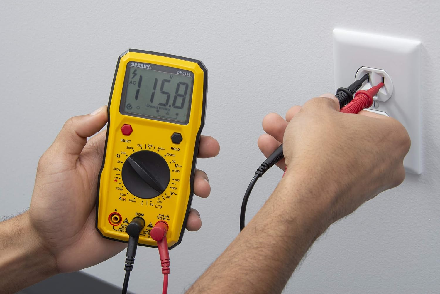
Figure 5.2: A user measuring the voltage of a AA battery with the DM6410 multimeter. The display shows a reading of 1.565 volts DC.
5.6 Data Hold Function
To freeze the current reading on the display, press the 'HOLD' button. Press it again to release the hold and resume live readings.
6. Maintenance
6.1 Cleaning
Wipe the meter with a damp cloth and mild detergent. Do not use abrasives or solvents. Keep the display clean and dry.
6.2 Battery Replacement
Refer to Section 4.1 for battery installation instructions. Replace batteries when the low battery indicator appears on the display to ensure accurate measurements.
6.3 Fuse Replacement
If the current measurement function fails, the fuse may need replacement. Only replace with fuses of the specified type and rating:
- For 'A' input: Fused 10A max, 10 sec EACH 15min.
- For 'mA µA' input: Fused max 200mA CAT II 600V.
WARNING: To prevent electric shock, remove test leads before opening the case or battery cover. Do not operate with the battery cover open.
7. Troubleshooting
If the multimeter is not functioning as expected, consider the following common issues:
- No Display: Check battery installation and ensure batteries are not depleted. Replace if necessary.
- Incorrect Readings: Verify that the correct function and range are selected for the measurement. Ensure test leads are properly connected and in good condition. Check battery level.
- Current Measurement Failure: Check the fuse for the current input jack being used. Replace if blown.
- 'OL' (Overload) Display: This indicates the measured value exceeds the selected range. Switch to a higher range or ensure the circuit is within the meter's capabilities.
If problems persist, contact customer support.
8. Specifications
| Specification | Detail |
|---|---|
| Brand | SPERRY |
| Model Number | DM6410 |
| Measurement Type | Digital Multimeter |
| Functions | 8 Function / 28 Manual Range |
| Voltage Rating | 600V AC / 1000V DC |
| Safety Rating | CAT III 600V, cETLus, CE |
| Power Source | 2 x AAA Batteries (Alkaline) |
| Display | 2000 Count LCD |
| Dimensions (L x W x H) | 2.9 x 1.75 x 3.8 inches |
| Item Weight | 13.1 ounces |
| Material | Plastic |
| UPC | 035632201143 |
9. Warranty
The Sperry Instruments DM6410 Digital Multimeter comes with a limited warranty. For specific details regarding warranty coverage and duration, please refer to the warranty card included with your product or visit the official Sperry Instruments website.
10. Support
For further assistance, technical support, or to view additional product information, please visit the official Sperry Instruments website or contact their customer service department.
You can find more information about Sperry products at: Sperry Instruments Store


