AUKUYEE Q15001
AUKUYEE Q15001 2.4" TFT Handheld Digital Oscilloscope Instruction Manual
Model: Q15001
1. Introduction
This manual provides detailed instructions for the safe and effective use of your AUKUYEE Q15001 2.4" TFT Handheld Digital Oscilloscope. This device is designed for measuring and analyzing electronic signals, offering portability and ease of use for various applications.

Figure 1: AUKUYEE Q15001 Handheld Digital Oscilloscope with included accessories.
The AUKUYEE Q15001 is a pre-assembled unit, eliminating the need for user assembly. It features an extended sensitivity range of 5mV/div to 20V/div, a rotary encoder for quick parameter adjustments, and waveform memory functionality. The design integrates the display and main control unit on a single board, with the analog channel on a separate board for improved signal separation.
2. What's Included
Upon unpacking, please verify that all items listed below are present:
- 1 x AUKUYEE Q15001 Handheld Digital Oscilloscope (assembled)
- 1 x BNC-clip cable
- 1 x Power adapter
- 1 x User Manual (this document)

Figure 2: Package contents including the oscilloscope, BNC-clip cable, and power adapter.
3. Product Features
- Extended Sensitivity: Measures signals from 5mV/div to 20V/div.
- Multiple Trigger Modes: Supports Auto, Normal, and Single trigger modes for capturing various waveforms.
- Rotary Encoder: Facilitates quick and easy parameter adjustments.
- Waveform Hold Function: Allows freezing the current waveform for detailed analysis.
- Waveform Memory: Retains the waveform even after power-off.
- Optimized Design: Display and Microcontroller Unit (MCU) are mounted on the same mainboard, with the analog channel on a separate board to minimize interference.
- Handheld and Portable: Compact design for convenient use in various environments.
- Pre-assembled: Ready to use out of the box, no assembly required.

Figure 3: Exploded view illustrating the internal component layout and modular design.
4. Setup
- Power Connection: Connect the provided power adapter to the DC 9V input port on the side of the oscilloscope. Ensure the power cable is securely inserted.
- Probe Connection: Attach the BNC-clip cable to the BNC connector (Signal Input) on the top of the oscilloscope. Connect the alligator clips to the circuit points you wish to measure.
- Power On: Flip the power switch to the 'ON' position. The display should illuminate.
- Initial Calibration: It is recommended to calibrate the oscilloscope before first use to ensure accurate measurements. Refer to the operating instructions for calibration procedures.
5. Operating Instructions
Familiarize yourself with the controls and display elements as shown in Figure 4:
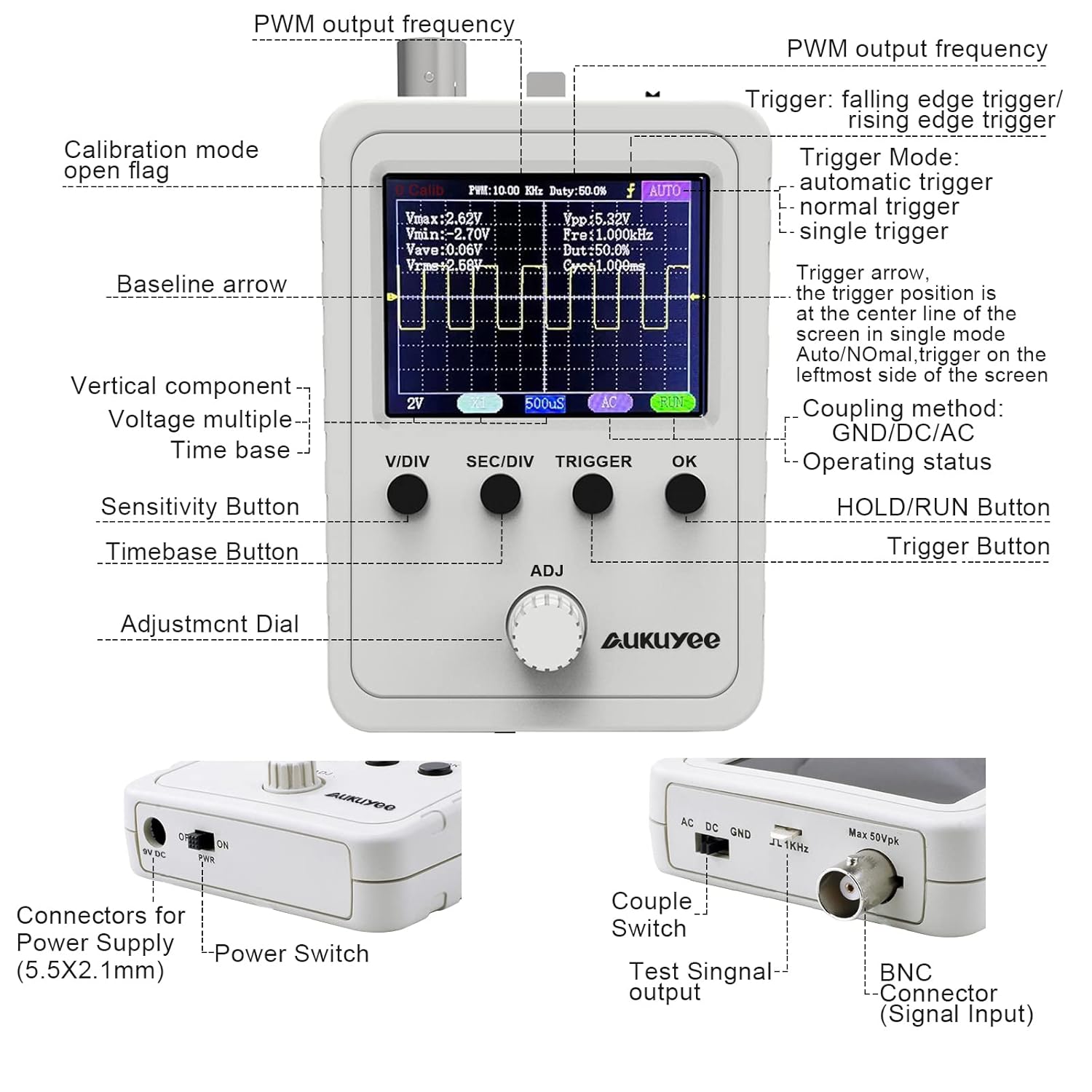
Figure 4: Front panel controls, display elements, and side connectors.
5.1. Controls Overview
- V/DIV Button: Adjusts the vertical sensitivity (voltage per division).
- SEC/DIV Button: Adjusts the horizontal time base (time per division).
- TRIGGER Button: Controls trigger settings (mode, level).
- OK Button: Used for confirmation, entering menus, or activating/deactivating functions (e.g., HOLD/RUN). Holding for 3 seconds may power ON/OFF the device.
- ADJ Dial (Rotary Encoder): Used to adjust selected parameters, navigate menus, or fine-tune settings.
- Power Switch: Turns the device ON/OFF.
- Couple Switch (AC/DC/GND): Selects the input coupling method.
- AC: Blocks DC components, showing only the AC portion of the signal.
- DC: Shows both AC and DC components of the signal.
- GND: Disconnects the input signal, displaying a zero-volt reference line.
- Test Signal Output: Provides a known test signal for calibration or testing probes.
5.2. Basic Measurement Steps
- Connect Probe: Attach the BNC-clip cable to the signal input and connect the clips to your circuit.
- Power On: Turn on the oscilloscope using the power switch.
- Adjust Vertical Scale (V/DIV): Press the V/DIV button and use the ADJ dial to set the appropriate voltage scale so the waveform fits vertically on the screen.
- Adjust Horizontal Scale (SEC/DIV): Press the SEC/DIV button and use the ADJ dial to set the appropriate time base so a few cycles of the waveform are visible horizontally.
- Set Coupling: Use the Couple Switch to select AC, DC, or GND depending on your measurement needs.
- Adjust Trigger:
- Press the TRIGGER button to cycle through trigger modes (Auto, Normal, Single). Auto mode is generally suitable for most signals.
- Use the ADJ dial to adjust the trigger level, ensuring the trigger point is stable on the waveform.
- Analyze Waveform: Once a stable waveform is displayed, you can read parameters like Vmax, Vmin, Vpp, Frequency, Duty Cycle, etc., from the display.
- Hold/Run: Press the OK button to toggle between HOLD (freezing the waveform) and RUN (continuous display).
5.3. Waveform Comparison (Old vs. New Interface)
The updated version of the oscilloscope features an improved interface for clearer display and easier parameter adjustment. Figure 5 illustrates the differences.
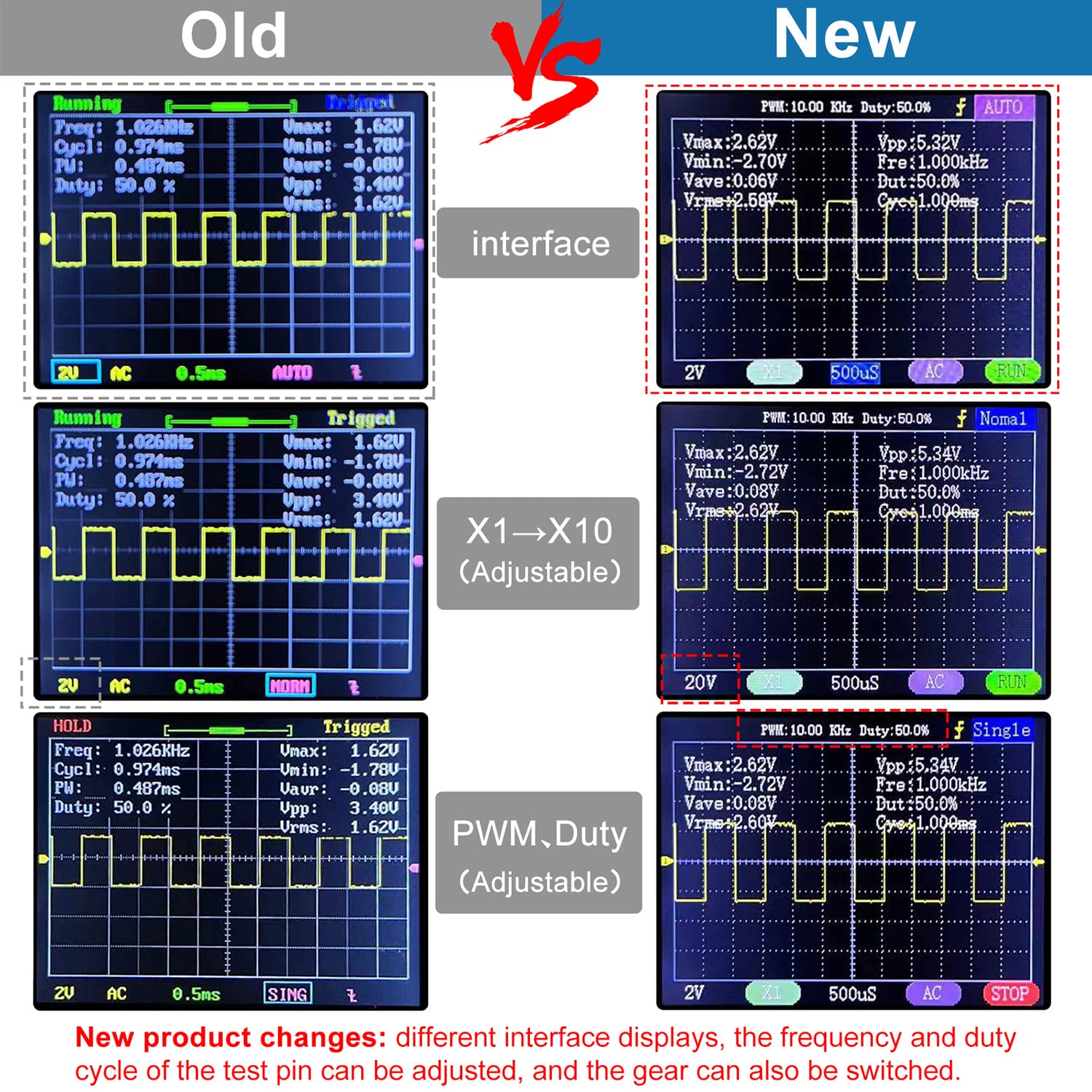
Figure 5: Comparison of the previous and current user interfaces.
6. Maintenance
- Cleaning: Use a soft, dry cloth to clean the device. Do not use abrasive cleaners or solvents.
- Storage: Store the oscilloscope in a dry, dust-free environment away from direct sunlight and extreme temperatures.
- Handling: Handle the device with care to avoid physical damage. While designed to be handheld, excessive force or dropping can cause internal damage.
- Power Adapter: Always use the provided power adapter. Ensure the adapter and cable are not damaged.
7. Troubleshooting
- Device does not power on:
- Ensure the power adapter is securely connected to both the oscilloscope and a working power outlet.
- Verify the power switch is in the 'ON' position.
- Check the power adapter and cable for any visible damage.
- Unstable or no waveform displayed:
- Check the BNC-clip cable connection to the oscilloscope and the circuit. Ensure it is secure.
- Adjust the V/DIV and SEC/DIV settings to bring the waveform into view and scale.
- Adjust the trigger level and trigger mode (try 'Auto' mode first).
- Ensure the input coupling (AC/DC/GND switch) is set correctly for your signal.
- Perform a calibration if the issue persists.
- Display appears glitchy at very large time divisions:
- This can be a characteristic of some digital oscilloscopes when viewing extremely slow signals. Try to adjust the time base to a more appropriate range if possible.
- Loose physical connections (e.g., BNC connector, power cable):
- Ensure all connectors are firmly seated. If a power cable is difficult to insert fully, inspect for any obstructions or molding issues.
- If screws appear loose, gently tighten them, being careful not to over-tighten.
8. Specifications
| Feature | Specification |
|---|---|
| Model | Q15001 |
| Display | 2.4" TFT Color Display |
| Vertical Sensitivity | 5mV/div - 20V/div |
| Trigger Modes | Auto, Normal, Single |
| Product Dimensions | 4.53 x 2.95 x 0.87 inches (11.5 x 7.5 x 2.2 cm) |
| Weight | 7.37 ounces (209 grams) |
| Manufacturer | AUKUYEE |
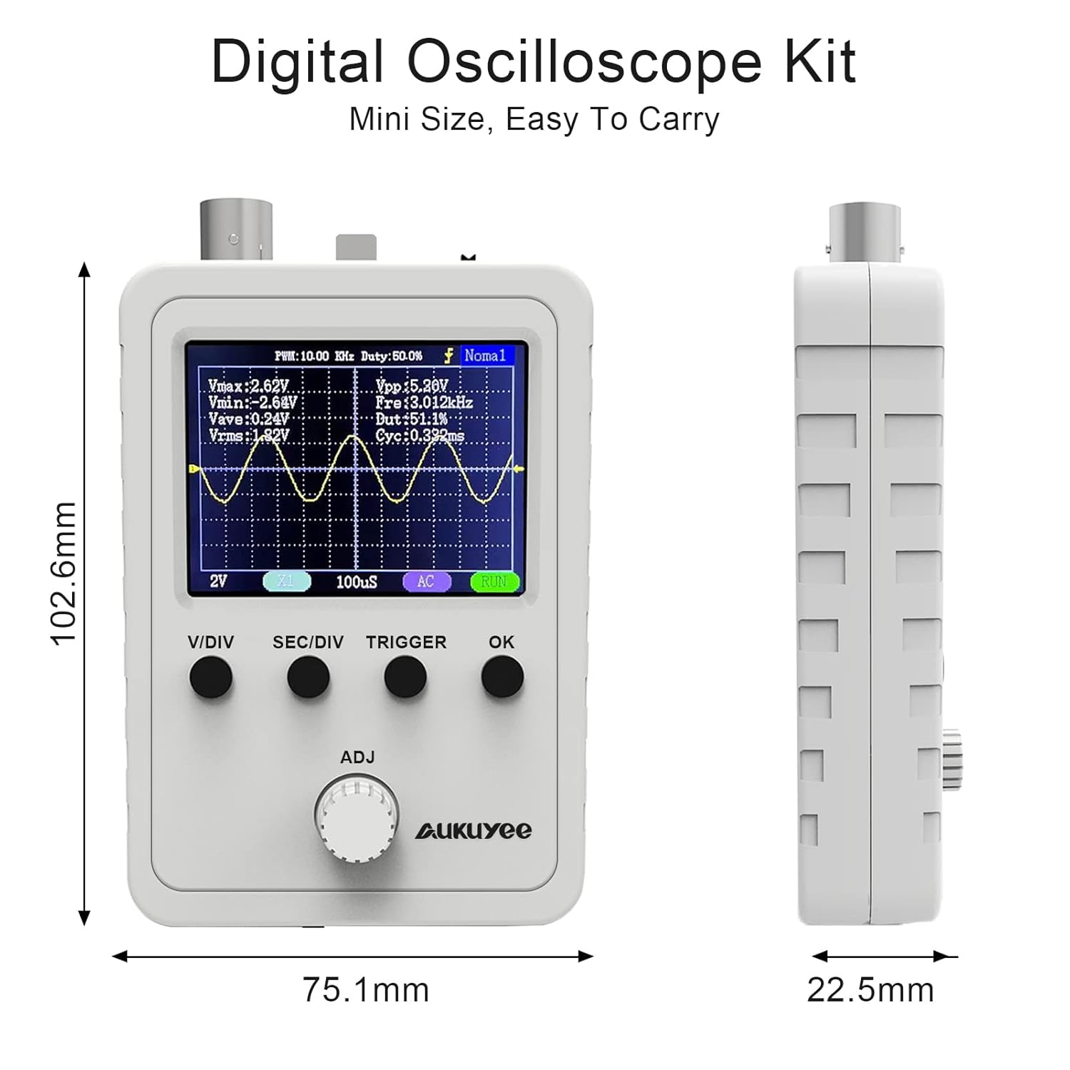
Figure 6: Physical dimensions of the oscilloscope.
9. Warranty and Support
For warranty information, technical support, or service inquiries, please contact AUKUYEE customer service through your purchase platform or the official AUKUYEE website. Please have your product model (Q15001) and purchase details available when contacting support.
10. Applications
The AUKUYEE Q15001 oscilloscope is suitable for a variety of applications, including:
- Electronics hobbyists and education
- Basic circuit debugging and testing
- Audio signal analysis
- Automotive diagnostics (low voltage signals)
- Transceiver signal monitoring

Figure 7: Various applications for the handheld oscilloscope.