1. Introduction and Overview
This manual provides detailed instructions for the installation, operation, and maintenance of your YAVIS RFID Access Control Kit. This kit is designed to provide secure access management for various applications, featuring a programmable metal keypad, an electric bolt lock, a power supply, an exit button, and RFID keyfobs.
Please read this manual thoroughly before installation and use to ensure proper functionality and safety.
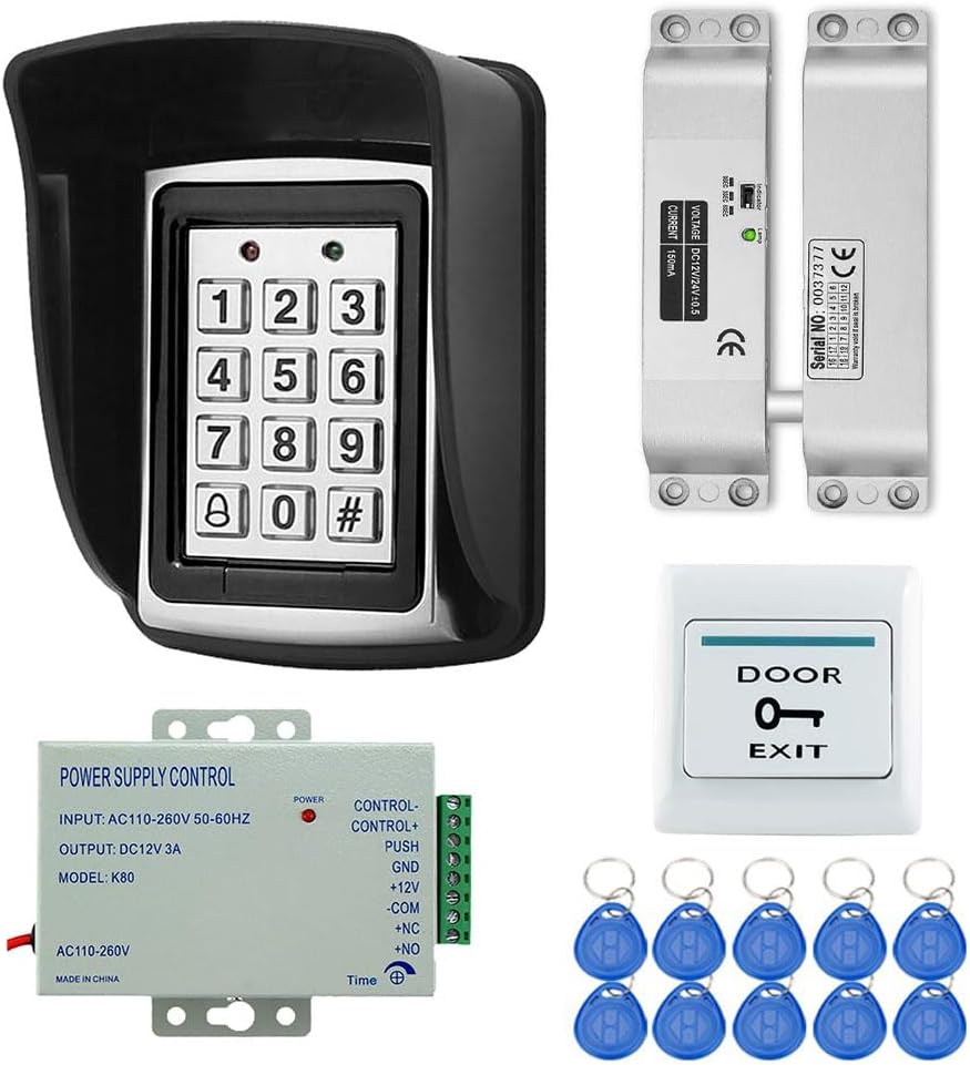
Figure 1: Overview of YAVIS RFID Access Control Kit components. This image displays the complete kit, including the waterproof keypad, electric bolt lock, power supply unit, exit button, and ten RFID keyfobs.
2. Product Components
The YAVIS RFID Access Control Kit includes the following main components:
- RFID Programmable Keypad: A metal, waterproof keypad for code entry and RFID card reading.
- Electric Bolt Lock: A secure electric drop bolt lock for door access control.
- DC 12V 3A Power Supply: Provides stable power to the access control system.
- Exit Button: For convenient egress from the secured area.
- RFID Keyfobs (10 pieces): For contactless access.
2.1 Keypad Details

Figure 2: Detailed view of the RFID keypad. This image highlights key features such as the work indicator lights, backlight button, back outlet for wiring, and fixed screw location.
- Work Indicator: LED lights indicating operational status.
- Backlight Button: Activates keypad backlight for low-light conditions.
- Back Outlet: Connection point for wiring.
- Fixed Screw: Secures the keypad in place.
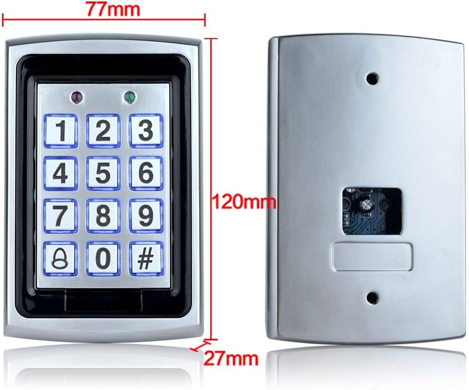
Figure 3: Dimensions of the RFID keypad. The keypad measures approximately 77mm in width, 120mm in height, and 27mm in depth.
2.2 Power Supply Details

Figure 4: Access Control Power Supply unit. This image shows the power supply with its input/output specifications and dimensions.
- AC Input: Standard AC100-240V 50-60Hz 36W.
- DC Output: Stabilizer DC12V/3A.
- Timing Control: Release time adjustable from 0-15 seconds.
- Dimensions: 120 mm x 95 mm x 38 mm.
- Outputs: NC/NO/COM for controlling various electric locks.
2.3 Electric Bolt Lock Details

Figure 5: Metal lock body structure of the electric drop bolt lock. This image details the lock's components and specifications.
- Voltage: 12VDC.
- Current: Start-up: 1.2A, Operating: 0.25A.
- Delay: Adjustable 0, 3, or 6 seconds (Factory setting: 0).
- Lock Mechanism: Locks with power, opens without power.
- Lock Type: Magnetic Sensor.
- Weight: 1KG.
- Size: 150mm x 34mm x 28mm.
2.4 RFID Keyfobs

Figure 6: RFID Keyfobs included in the kit. These are waterproof 125KHz ID keyfobs with a reading distance of 3-10cm. The kit includes 10 blue keyfobs.
- Frequency: 125KHz.
- Waterproof: Yes.
- Reading Distance: 3-10 cm.
- Type: Read only.
- Quantity: 10 pieces.
3. Specifications
| Feature | Detail |
|---|---|
| Manufacturer | YAVIS |
| Model Number | K7612+xiaoxing kit |
| Product Dimensions | 22 x 15 x 12 cm |
| Product Weight | 900 grams |
| Power Source | Wired (Cable électrique) |
| Input Voltage | AC100-240V (Power Supply) |
| Output Voltage | DC12V 3A (Power Supply) |
| Installation Method | Professional Hard Wire |
| Compatible Devices | EM Card |
| Connectivity Technology | Wired |
| Alert Type | Audio and Movement |
| Control Method | Touch |
| Keypad Material | Metal |
| Keypad Waterproof | Yes |
| RFID Keyfob Frequency | 125KHz |
| RFID Keyfob Reading Distance | 3-10 cm |
| Electric Lock Type | Drop Bolt Lock (Magnetic Sensor) |
| Electric Lock Delay | 0, 3, 6 seconds adjustable |
4. Setup and Installation
Proper installation is crucial for the reliable operation of your access control system. It is recommended that installation be performed by a qualified professional.
4.1 Wiring Diagram
Refer to the following wiring diagram for connecting the components of your access control system. Ensure all connections are secure and correctly matched to avoid damage to the devices.

Figure 7: Comprehensive wiring diagram for the YAVIS Access Control Kit. This diagram illustrates how to connect the power supply, access controller (keypad), electric mortise lock, electronic lock, magnetic lock, and exit button. Note the connections for +12V, GND, PUSH, NO, NC, and COM terminals.
- Power Supply Connections: Connect AC input to a standard power outlet. Connect DC output (12V, GND) to the access controller and electric lock as shown.
- Access Controller (Keypad) Connections: Connect to the power supply and the electric lock. The diagram shows connections for +12V, GND, PUSH, and lock control signals (NO/NC/COM).
- Electric Lock Connections: Connect the electric bolt lock to the power supply and the access controller's lock control outputs (NO/NC/COM) based on your lock's requirements (e.g., 'Lock with power' or 'Open without power').
- Exit Button Connections: Connect the exit button to the PUSH and GND terminals on the power supply or access controller, as indicated in the diagram.
- Time Adjustment: The power supply allows for a 0-15 second delay adjustment for the lock release.
4.2 Typical Installation Scenario
The following image provides an example of how the components can be physically installed on a door.
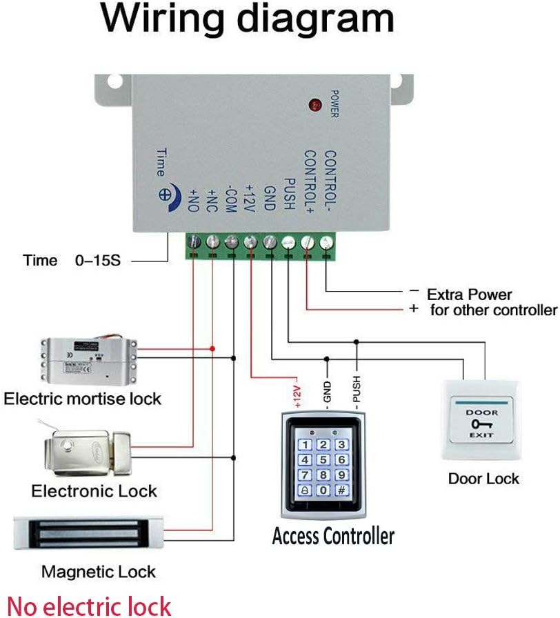
Figure 8: Example of an access control system installation on a door. This image shows the access controller (keypad) mounted on the exterior, the exit button on the interior, and the power supply unit connected to the electric drop lock (not included in this specific kit, but shown for context of a complete system).
Ensure the keypad is mounted at an accessible height and the electric lock is securely installed within the door frame or on the door itself, depending on the lock type. The exit button should be placed on the inside of the door for easy exit.
5. Operating Instructions
This section outlines the basic operation of the YAVIS RFID Access Control Kit.
5.1 Initial Setup and Programming
Upon initial power-up, the system will be in a default state. You will need to program administrator codes and user access credentials (codes or RFID cards).
- Enter Programming Mode: Typically, this involves entering a default master code (refer to the specific keypad model's detailed programming guide for the default code and exact steps).
- Change Master Code: For security, immediately change the default master code to a new, strong code.
- Add User Codes: Follow the programming instructions to add individual user PIN codes (4-6 digits).
- Add RFID Cards: Present each RFID keyfob to the keypad's reader when prompted in programming mode to enroll them.
- Exit Programming Mode: Save changes and exit programming mode.
Note: Specific programming steps may vary slightly depending on the keypad's firmware version. Always consult the dedicated programming manual for your keypad model for precise instructions.
5.2 Granting Access
- Using a PIN Code: Enter your valid PIN code on the keypad, followed by the '#' key. The lock will disengage for the programmed delay time.
- Using an RFID Keyfob: Present an enrolled RFID keyfob to the RFID reader area on the keypad. The lock will disengage for the programmed delay time.
- Using the Exit Button: From the inside, press the exit button. The lock will disengage immediately.
5.3 Lock Delay Adjustment
The electric bolt lock's delay time (how long it stays unlocked) can be adjusted on the power supply unit (0-15 seconds) and on the lock itself (0, 3, or 6 seconds). Ensure these settings are synchronized and meet your security requirements.
6. Maintenance
Regular maintenance helps ensure the longevity and reliable performance of your access control system.
- Cleaning: Wipe the keypad and other visible components with a soft, damp cloth. Avoid abrasive cleaners or solvents.
- Connection Check: Periodically inspect all wiring connections to ensure they are secure and free from corrosion or damage.
- Lock Mechanism: Ensure the electric bolt lock operates smoothly. Keep the bolt and strike plate free from obstructions.
- Software/Firmware: If applicable, check the manufacturer's website for any firmware updates for the keypad.
7. Troubleshooting
If you encounter issues with your YAVIS RFID Access Control Kit, refer to the following troubleshooting guide:
| Problem | Possible Cause | Solution |
|---|---|---|
| Keypad not responding / No power | No power to the system; loose wiring; faulty power supply. | Check power outlet and power supply connections. Verify power supply output voltage. Inspect all wiring for damage or loose connections. |
| Lock does not open with valid code/card | Incorrect wiring to the lock; lock mechanism obstructed; code/card not programmed correctly; faulty lock. | Review wiring diagram (Figure 7) and ensure correct lock connections (NO/NC/COM). Clear any obstructions around the lock. Re-program the user code/card. Test the lock independently if possible. |
| RFID keyfob not read | Keyfob not enrolled; keyfob damaged; reader malfunction. | Ensure the keyfob is properly enrolled in the system. Try another enrolled keyfob. Ensure the keyfob is presented within the reading distance (3-10cm). |
| Exit button not working | Incorrect wiring; faulty button. | Check exit button wiring to the power supply or access controller. Test the button for continuity if possible. |
| Lock remains unlocked or locked indefinitely | Incorrect lock delay setting; lock type (NO/NC) mismatch with wiring. | Adjust the lock delay setting on the power supply and/or the lock itself. Verify that the lock's operating mode (e.g., 'Lock with power' or 'Open without power') matches the wiring to the access controller's NO/NC terminals. |
If the problem persists after attempting these solutions, please contact YAVIS customer support or a qualified technician.
8. Warranty and Support
Specific warranty information for the YAVIS RFID Access Control Kit is not provided within this manual. Please refer to your purchase documentation or contact YAVIS customer service for details regarding warranty coverage and support.
For technical assistance or further inquiries, please visit the official YAVIS website or contact their support channels.
- Spare Parts: Information regarding the availability of spare parts is not provided.


