Walfront MS5908A
Walfront MS5908A Circuit Analyzer
User Manual
1. Introduction
The Walfront MS5908A Circuit Analyzer is a professional-grade instrument designed for comprehensive electrical circuit testing. It provides accurate measurements for various electrical parameters, ensuring safety and efficiency in electrical installations and troubleshooting. This manual provides detailed instructions for the proper use, maintenance, and care of your MS5908A Circuit Analyzer.

Figure 1.1: The Walfront MS5908A Circuit Analyzer and its detachable power cable.
2. Safety Information
Always adhere to the following safety precautions to prevent personal injury or damage to the instrument:
- Read and understand all instructions before using the device.
- Do not use the analyzer if it appears damaged or is operating abnormally.
- Ensure the power source matches the specified voltage range (AC100-240V).
- Always disconnect the device from the power source before cleaning or servicing.
- Avoid using the device in wet or damp conditions.
- Do not attempt to open or modify the device. Refer all servicing to qualified personnel.
- Wear appropriate personal protective equipment (PPE) when working with electrical circuits.
3. Product Components and Overview
Familiarize yourself with the various parts of the MS5908A Circuit Analyzer:
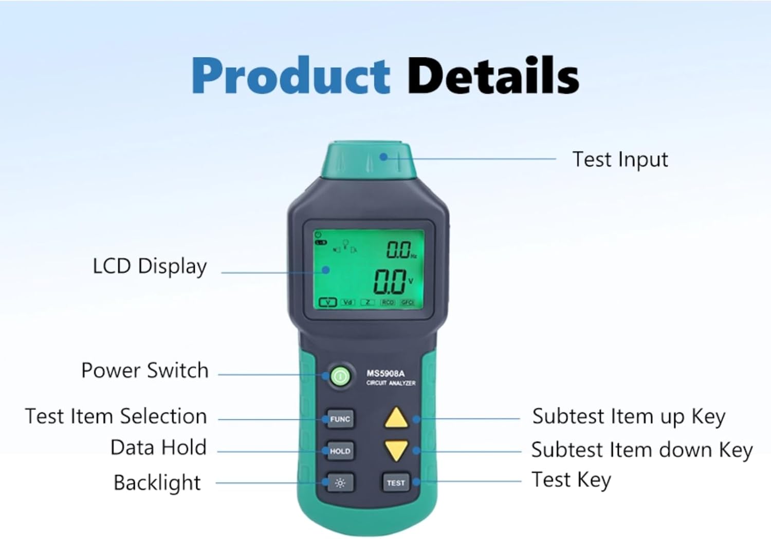
Figure 3.1: Key components of the MS5908A Circuit Analyzer.
- Test Input: The port where the power cable is connected to the circuit under test.
- LCD Display: Shows measurement readings, indicators, and menu options.
- Power Switch: Turns the device ON or OFF.
- FUNC Button: Selects different test items or functions.
- HOLD Button: Freezes the current reading on the display.
- Backlight Button: Activates or deactivates the display backlight.
- Up/Down Arrow Keys: Navigate through subtest items or adjust settings.
- TEST Button: Initiates a test or confirms a selection.
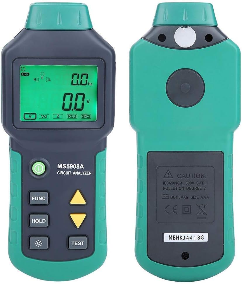
Figure 3.2: Front and rear views of the MS5908A Circuit Analyzer.
4. Setup
Before using the MS5908A, ensure it is properly prepared:
4.1. Battery Installation
The MS5908A requires six (6) AA batteries for operation. Batteries are not included with the device.
- Locate the battery compartment on the back of the unit.
- Using a screwdriver, carefully remove the screw securing the battery cover.
- Remove the battery cover.
- Insert six AA batteries, observing the correct polarity (+/-) as indicated inside the compartment.
- Replace the battery cover and secure it with the screw.

Figure 4.1: Battery compartment for six AA batteries.
4.2. Connecting the Power Cable
Connect the provided power cable to the test input port at the bottom of the analyzer and then to the electrical outlet you wish to test.

Figure 4.2: Power input port on the MS5908A.

Figure 4.3: US standard three-prong plug.
5. Operating Instructions
The MS5908A offers various measurement functions. Follow these steps for accurate readings:
5.1. Powering On and Basic Voltage Measurement
- Ensure batteries are installed and the power cable is connected to the analyzer.
- Plug the analyzer's power cable into the electrical outlet to be tested.
- Press the Power Switch to turn on the device. The LCD display will illuminate.
- The device will automatically display the TRMS AC Voltage and Frequency.
5.2. Identifying 3-Wire Socket Connection Mode
This function helps verify correct wiring of a 3-wire socket (neutral for left, live for right, and presence of earth wire).
- With the device powered on and connected to the socket, press the FUNC button repeatedly until the "Socket Connection Mode" indicator appears on the display.
- The display will show the detected wiring configuration. Refer to the device's on-screen indicators for interpretation (e.g., correct wiring, open ground, open neutral, hot/neutral reverse).
5.3. Measuring Wire Drop (Artificial Load Test)
This test measures voltage drop under a simulated load, indicating the health of the wiring. For MS5908A, available loads are 12A, 15A, and 20A.
- Connect the analyzer to the circuit.
- Press the FUNC button until the "Wire Drop" or "Load Test" mode is selected.
- Use the Up/Down Arrow Keys to select the desired artificial load (12A, 15A, or 20A).
- Press the TEST button to initiate the load test. The display will show the voltage drop.
- Caution: Do not run the load test for extended periods to prevent overheating or circuit overload.
5.4. Measuring Phase Voltage, Neutral Wire, Voltage to Earth, Peak Voltage, and Frequency
These measurements provide detailed insights into the quality of the power supply.
- With the device connected and powered on, press the FUNC button to cycle through the available measurement modes.
- The display will show readings for:
- Phase Voltage (Live to Neutral)
- Neutral Wire Voltage (Neutral to Earth)
- Voltage to Earth (Live to Earth)
- Peak Voltage
- Frequency (Hz)
- Use the HOLD button to freeze any reading for closer inspection. Press HOLD again to release.
5.5. Measuring Conductor Impedance (Live, Neutral, Earth)
This function measures the impedance of the live (phase), neutral, and earth wires, which is crucial for assessing circuit integrity and fault current paths.
- Connect the analyzer to the live circuit.
- Press the FUNC button until the "Impedance" or "Z" mode is selected.
- The display will show the impedance values for the live, neutral, and earth conductors.
5.6. GFCI/RCD Fault Testing
The MS5908A can test Ground Fault Circuit Interrupters (GFCIs) and Residual Current Devices (RCDs) to ensure they trip correctly, providing critical safety verification.
- Connect the analyzer to the GFCI/RCD protected outlet.
- Press the FUNC button until the "GFCI" or "RCD" test mode is selected.
- Press the TEST button. The device will simulate a fault condition.
- Observe if the GFCI/RCD trips. A successful trip indicates proper functioning.
- If the GFCI/RCD does not trip, it indicates a fault or malfunction, and the circuit should be inspected by a qualified electrician.
- Reset the GFCI/RCD after the test.
6. Maintenance
Proper maintenance ensures the longevity and accuracy of your MS5908A Circuit Analyzer:
- Cleaning: Wipe the device with a soft, dry cloth. Do not use abrasive cleaners or solvents. Ensure the device is disconnected from any power source before cleaning.
- Storage: Store the analyzer in a cool, dry place away from direct sunlight and extreme temperatures. If storing for an extended period, remove the batteries to prevent leakage.
- Battery Replacement: Replace batteries when the low battery indicator appears on the display. Always replace all six batteries simultaneously with new ones of the same type.
- Calibration: For professional use, periodic calibration by a certified laboratory is recommended to maintain measurement accuracy.
7. Troubleshooting
If you encounter issues with your MS5908A Circuit Analyzer, refer to the following common problems and solutions:
| Problem | Possible Cause | Solution |
|---|---|---|
| Device does not power on. | Dead or incorrectly installed batteries. | Check battery polarity; replace all batteries. |
| Inaccurate readings. | Poor connection; device malfunction; environmental factors. | Ensure secure connection; re-test; if problem persists, contact support. |
| GFCI/RCD test does not trip. | Faulty GFCI/RCD; incorrect test procedure. | Ensure correct test mode; if GFCI/RCD still doesn't trip, it may be faulty and requires professional inspection. |
| Display is dim or flickering. | Low battery power. | Replace batteries. |
If the problem persists after attempting these solutions, please contact Walfront customer support.
8. Specifications
Technical specifications for the Walfront MS5908A Circuit Analyzer:
| Parameter | Value |
|---|---|
| Model | MS5908A |
| Brand | Walfront |
| Power Source | Corded Electric (for testing), 6x AA Batteries (for device operation) |
| Operating Voltage Range | AC100-240V (Min. Operating Voltage: 85V AC) |
| Artificial Load (MS5908A) | 12A, 15A, 20A |
| Dimensions (L x W x H) | 7.68 x 3.15 x 1.38 inches (19.5 x 8 x 3.5 cm) |
| Item Weight | 1.3 pounds (approx. 0.59 kg) |
| Color | Green |
| Country of Origin | China |
| UPC | 749249628865 |
| Internal Model Number | Wal fronti6sp8erauz-01 |

Figure 8.1: Dimensions of the MS5908A Circuit Analyzer.
9. Warranty and Support
Walfront products are manufactured to high-quality standards. For information regarding warranty coverage, technical support, or service, please refer to the contact information provided with your purchase or visit the official Walfront website. Please retain your proof of purchase for warranty claims.
For further assistance, you may contact Walfront customer service through their official channels. When contacting support, please have your product model (MS5908A) and purchase details ready.
Related Documents - MS5908A
 |
Pressure Threshold Switch Circuit Guide - WALFRONT S40 Technical guide for the WALFRONT S40 pressure threshold switch, explaining the Wheatstone bridge and voltage comparator circuit operation. |
 |
Product Manual: WALFRONT Electronic Transformer ESDB332.11 User manual and compliance information for the WALFRONT Electronic Transformer model ESDB332.11, including manufacturer details and usage instructions. |
 |
User Manual: 12V/24V/36V 15A PWM DC Motor Speed Controller (GS00574) Operational guide and safety instructions for the GS00574 PWM DC Motor Speed Controller, featuring specifications and usage guidelines. |
 |
User Manual: Mini Cordless Rotating Tool Kit (Model 10112402562) User manual for the WALFRONT Mini Cordless Rotating Tool Kit, featuring 5-speed settings, USB charging, and usage instructions for engraving, sanding, and grinding. |
 |
WALFRONT DC Motor Speed Regulator User Manual (10102500106) User manual for the WALFRONT DC Motor Speed Regulator (Model 10102500106), featuring wireless remote control, 6V-28V PWM stepless speed regulation, and 5A capacity. |
 |
User Manual for WALFRONT 7.5KV 30mA Neon Light Electronic Transformer (NP-7500-30) User manual and safety instructions for the WALFRONT 7.5KV 30mA NP-7500-30 Neon Light Electronic Transformer. Includes manufacturer and compliance details. |
Ask a question about this manual
Ask about setup, troubleshooting, compatibility, parts, safety, or missing instructions. Manuals+ will review the question and use this page’s manual context to help answer it.