1. Introduction
Thank you for choosing the MUSETEX G08 ATX Mid Tower PC Case. This manual provides detailed instructions for the proper installation, operation, and maintenance of your new computer case. The G08 case is designed for high-performance systems, featuring four pre-installed PWM ARGB fans, double tempered glass panels, and a structural design optimized for airflow and component compatibility.
Please read this manual thoroughly before beginning installation to ensure correct assembly and to maximize the lifespan and performance of your components.

Figure 1: MUSETEX G08 ATX Mid Tower PC Case
2. Safety Information
Observe the following safety precautions during installation and operation:
- Always disconnect the power supply from the wall outlet before installing or servicing any components inside the PC case.
- Handle tempered glass panels with care. Although durable, they can break if subjected to sharp impacts or excessive force.
- Wear an anti-static wrist strap or frequently touch a grounded metal object to discharge static electricity, which can damage sensitive electronic components.
- Keep small parts and screws away from children.
- Ensure proper ventilation around the PC case to prevent overheating.
- Avoid placing the PC case in direct sunlight or near heat sources.
3. Package Contents
Verify that all items are present in your package:
- MUSETEX G08 ATX Mid Tower PC Case
- 4 x Pre-installed PWM ARGB Fans
- Accessory box (containing screws, cable ties, and other small parts)
- User Manual (this document)
Note: Additional components such as a remote control for fans may be included depending on the specific product bundle.
4. Setup Instructions
4.1 Preparing the Case
Before installing components, remove the tempered glass side panel. The side panel is typically hinged or secured with thumb screws. Handle with care.

Figure 2: Opening the Tempered Glass Side Panel
4.2 Motherboard Installation
The G08 case supports ATX, Micro ATX, and Mini ITX motherboards. Motherboard standoffs are pre-installed for ATX motherboards. Adjust or install additional standoffs as needed for your specific motherboard size.
- Align your motherboard with the standoffs in the case.
- Secure the motherboard using the provided screws.
4.3 GPU and Component Clearance
The case supports GPUs up to 390mm (15.35 inches) in length. Ensure your GPU fits within these dimensions. The case also supports horizontal and vertical GPU mounting options.
For CPU coolers, a maximum height of 176mm is supported. Radiator support includes 280mm/240mm on top and 120mm/140mm on the rear.

Figure 3: Internal Component Layout and Clearance

Figure 4: Case Dimensions and Component Max Sizes

Figure 5: Fan and Radiator Support
4.4 Storage Drive Installation
The G08 case provides ample space for storage drives, supporting up to 4 drives. There are dedicated locations for HDDs and SSDs.

Figure 6: Storage Drive Mounting Locations
4.5 Fan Installation and Adjustment
The case comes with 4 pre-installed PWM ARGB fans. The fan mounts have wider cutouts, allowing for adjustment of fan positions as needed for optimal airflow or component clearance.

Figure 7: Adjustable Fan Positions
4.6 Cable Management
The G08 case is designed with features to assist with cable management, including space behind the motherboard tray and cutouts for routing cables. Utilize cable ties (often included in the accessory box) to keep cables neat and organized, which improves airflow and aesthetics.
4.7 I/O Panel Connections
Connect the front I/O panel cables (USB 3.0, HD Audio, Power Switch, Reset Switch, HDD LED, Power LED) to the corresponding headers on your motherboard. Refer to your motherboard manual for exact header locations.

Figure 8: Front I/O Panel
5. Operating Instructions
5.1 Powering On
Once all components are installed and cables are connected, close the side panel. Connect the power cable to your power supply and a wall outlet. Press the power button on the front I/O panel to start your system.
5.2 Fan Control (PWM)
The pre-installed fans are PWM (Pulse Width Modulation) enabled, meaning their speed can be adjusted based on system temperature or manual settings. This allows for optimized cooling performance and reduced noise levels.

Figure 9: PWM Fan Speed Adjustment
5.3 ARGB Lighting Control
The fans feature Addressable RGB (ARGB) lighting with 16.8 million colors. You can control the lighting in two primary ways:
- Motherboard RGB Software Sync: If your motherboard has a 5V 3-pin ARGB header, you can connect the fan controller to it and synchronize the lighting with your motherboard's RGB software (e.g., ASUS Aura Sync, MSI Mystic Light Sync, GIGABYTE RGB Fusion, ASRock Polychrome RGB). To activate motherboard control, hold down the RGB button on top of the case until the RGB blinks.
- Dedicated Controller/Remote: The case includes a fan controller. If a remote control is provided, use it to cycle through various lighting modes and colors.

Figure 10: Motherboard RGB Software Sync

Figure 11: 5V 3-Pin ARGB Header Connection
5.4 I/O Panel Usage
The front I/O panel provides convenient access to:
- USB 3.0 Ports (x2): For high-speed data transfer with compatible devices.
- HD Audio Jacks: For connecting headphones and microphones. The HD Audio features a signal shielding net to prevent noise interference.
- Power Button: To turn the system on/off.
- Reset Button: To restart the system.
6. Maintenance
Regular maintenance helps ensure optimal performance and longevity of your PC components.
6.1 Dust Filter Cleaning
The G08 case includes magnetic dust filters on the top and a pull-out dust filter on the bottom. These filters prevent dust buildup inside the case.
- Periodically remove the dust filters.
- Clean them using compressed air, a soft brush, or by rinsing with water (ensure they are completely dry before re-installation).
- Re-attach the filters.
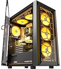
Figure 12: Magnetic Top Dust Filter

Figure 13: Pull-out Bottom Dust Filter
6.2 General Cleaning
Use a soft, damp cloth to clean the exterior surfaces of the case. Avoid abrasive cleaners or solvents that could damage the finish or tempered glass.
7. Troubleshooting
This section addresses common issues you might encounter.
7.1 Fans Not Spinning or RGB Not Working
- Check Connections: Ensure all fans are properly connected to the fan controller, and the fan controller is connected to the power supply (SATA power) and, if applicable, to the motherboard's 5V 3-pin ARGB header.
- Motherboard Sync: If using motherboard RGB software, ensure you have activated motherboard control by holding the RGB button on the case until the lights blink.
- Remote Control: If using a remote, check its battery and ensure it's pointed towards the controller.
- Motherboard Compatibility: For ARGB sync, your motherboard must have a 5V 3-pin ARGB interface. A 12V 4-pin RGB header is not compatible with ARGB.
7.2 Tight Cable Management
The space behind the motherboard tray can be tight, especially with thicker or braided cables. Plan your cable routing carefully before securing components. Use the provided cable ties to bundle cables neatly.
7.3 Missing HDD Caddy
If you find that a hard drive caddy is missing or you require additional ones, please contact MUSETEX customer support for assistance.
8. Specifications
| Feature | Detail |
|---|---|
| Brand | MUSETEX |
| Model Name | G08 |
| Case Type | Mid Tower |
| Motherboard Compatibility | E-ATX/ATX/M-ATX/ITX |
| Material | Metal, Plastic, Tempered Glass |
| Color | Black |
| Item Dimensions (D x W x H) | 16.34"D x 8.46"W x 17.52"H |
| Item Weight | 17.55 Pounds |
| Pre-installed Fans | 4 x PWM ARGB Fans (120mm) |
| Cooling Method | Air, Water |
| Max GPU Length | 390mm (15.35 inches) |
| Max CPU Cooler Height | 176mm |
| Radiator Support (Top) | 280mm/240mm |
| Radiator Support (Rear) | 120mm/140mm |
| Storage Bays | 4 (HDD/SSD) |
| Front I/O Ports | 2 x USB 3.0, HD Audio |
| Special Features | RGB Fans, Double Tempered Glass, Magnetic Dust Filters |
9. Warranty Information
The MUSETEX G08 ATX Mid Tower PC Case comes with a 1-year warranty from the date of purchase. This warranty covers manufacturing defects and issues arising from normal use. It does not cover damage caused by misuse, accidents, unauthorized modifications, or improper installation.
Please retain your proof of purchase for warranty claims.
10. Customer Support
For any questions, technical assistance, or warranty claims regarding your MUSETEX G08 PC Case, please contact MUSETEX customer support. You can typically find contact information by clicking on "Sold by MUSETEX" on the product's purchase page or by visiting the official MUSETEX brand store.

Figure 14: Locating Customer Support Information
Video 1: Overview of MUSETEX PC Case Features. This video provides a visual demonstration of the case's design and functionality.