1. Introduction
This manual provides instructions for the installation, operation, and maintenance of the Teletek LCD63VG Remote LCD Keypad. This keypad is designed for use with the CA62 control panel, offering a clear blue icon display and advanced features for security system management.
2. Safety Information
Read all instructions carefully before installation and operation. Failure to follow these instructions may result in damage to the device or personal injury. Keep this manual for future reference.
- Ensure power is disconnected from the control panel before installation or servicing.
- Installation should be performed by qualified personnel only.
- Do not expose the device to moisture, extreme temperatures, or direct sunlight.
- Do not attempt to open or repair the device yourself. Refer all servicing to authorized personnel.
3. Product Features
The Teletek LCD63VG LCD Keypad offers the following key features:
- Blue LCD display with icon indicators.
- Voice guide functionality with 7 distinct voice messages.
- Supports 1 programmable zone.
- Display for up to 12 zones and 2 partitions.
- Quick button combination for sending PANIC alarm messages to a monitoring station.
4. Package Contents
Verify that all items are present in the package:
- Teletek LCD63VG LCD Keypad
- Mounting hardware (screws, wall plugs)
- User Manual (this document)
5. Installation and Setup
5.1 Mounting the Keypad
- Choose a suitable indoor location, away from direct sunlight, moisture, and extreme temperatures.
- Mark the drilling points on the wall using the keypad's backplate as a template.
- Drill holes and insert wall plugs if necessary.
- Secure the keypad's backplate to the wall using the provided screws.
5.2 Wiring Connections
Connect the keypad to the CA62 control panel according to the wiring diagram provided in the CA62 control panel's manual. Ensure correct polarity for power connections and proper data line connections.
- Power: Connect the keypad's power terminals to the control panel's auxiliary power output.
- Data: Connect the keypad's data terminals to the control panel's data bus.
- Zone Input: If utilizing the programmable zone, connect the desired sensor to the keypad's zone input terminals.
5.3 Initial Power-Up and Configuration
- After all wiring is complete, apply power to the CA62 control panel.
- The keypad display should illuminate. Follow the instructions in the CA62 control panel manual for keypad enrollment and system programming.
- Configure the programmable zone and voice messages as required by your security system setup.
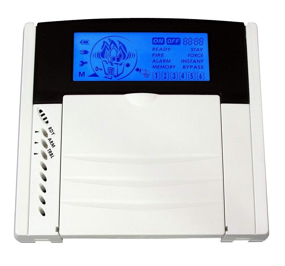
Figure 1: Front view of the Teletek LCD63VG LCD Keypad. This image shows the blue LCD screen and the numeric and function buttons.
6. Operating Instructions
The LCD63VG keypad provides an interface for managing your CA62 security system. Refer to your CA62 control panel manual for specific system commands and programming details.
6.1 Arming and Disarming
- To Arm: Enter your user code followed by the ARM button (or equivalent as programmed in CA62).
- To Disarm: Enter your user code followed by the DISARM button (or equivalent).
6.2 Zone Status Display
The LCD display shows the status of up to 12 zones and 2 partitions. Icons will indicate armed, disarmed, open, or alarm conditions. Consult the CA62 manual for icon interpretations.
6.3 Voice Guide
The keypad features a voice guide with 7 pre-recorded messages to assist with system operations and status notifications. These messages are activated during specific events or user interactions as configured in the control panel.
6.4 Panic Alarm
In an emergency, press the designated quick button combination (as specified in your CA62 manual) to send a PANIC alarm message to the monitoring station. This feature is typically activated by pressing two specific function keys simultaneously.
7. Maintenance
The Teletek LCD63VG LCD Keypad requires minimal maintenance.
- Cleaning: Wipe the keypad surface with a soft, dry cloth. Do not use abrasive cleaners or solvents.
- Inspection: Periodically check the keypad for any signs of damage or loose connections.
- Firmware Updates: Any firmware updates for the keypad are typically managed through the connected CA62 control panel. Refer to the CA62 manual for details.
8. Troubleshooting
If you encounter issues with your LCD63VG keypad, refer to the following common problems and solutions:
| Problem | Possible Cause | Solution |
|---|---|---|
| Keypad display is blank. | No power or loose connection. | Check power supply to the CA62 control panel. Verify keypad wiring connections. |
| Keypad not responding to input. | Keypad not enrolled or data line issue. | Ensure keypad is correctly enrolled in the CA62 system. Check data line connections. |
| Voice guide not working. | Feature disabled or volume too low. | Check CA62 control panel settings for voice guide activation and volume levels. |
| Incorrect zone status displayed. | Sensor issue or wiring problem. | Verify the sensor connected to the zone. Check wiring between the sensor and the keypad/control panel. |
If the problem persists after attempting these solutions, contact Teletek technical support or your security system installer.
9. Specifications
| Parameter | Value |
|---|---|
| Model Number | LCD63VG |
| Manufacturer | Teletek |
| Display Type | Blue LCD with icons |
| Compatible Control Panel | CA62 |
| Zones Supported | 12 (display), 1 (programmable) |
| Partitions Supported | 2 |
| Voice Guide Messages | 7 |
| Item Weight | 320 grams |
10. Warranty and Support
10.1 Warranty Information
Teletek products are manufactured to high-quality standards. For specific warranty terms and conditions, please refer to the warranty card included with your product or visit the official Teletek website. Keep your proof of purchase for warranty claims.
10.2 Technical Support
For technical assistance, installation queries, or troubleshooting beyond the scope of this manual, please contact your authorized Teletek dealer or visit the Teletek official support portal. Ensure you have your product model number (LCD63VG) and serial number ready when contacting support.
Online Resources: For additional documentation and FAQs, please visit the Teletek Electronics website.


