1. Introduction
The ABB ATS010 is an Automatic Transfer Switch (ATS) designed to manage power supply by automatically switching between a normal power source and an emergency power source, such as a generator. This device ensures continuous power availability for critical loads, enhancing system reliability. This manual provides instructions for its proper installation, operation, and maintenance.
2. Safety Information
WARNING: Installation and servicing of this equipment must be performed by qualified electrical personnel only. Failure to follow these instructions can result in serious injury or death. Always disconnect all power sources before working on the ATS010 unit.
- Ensure all local and national electrical codes are followed.
- Verify proper grounding of the equipment.
- Do not operate the unit with damaged components.
- Keep the unit free from moisture and extreme temperatures.
3. Product Overview
The ABB ATS010 features a robust design for reliable power transfer. Key components include control logic, status indicators, and connection terminals for normal and emergency power lines.

Figure 1: Front view of the ABB ATS010 control panel.

Figure 2: Angled front view of the ABB ATS010.
4. Setup and Installation
Installation of the ATS010 requires professional electrical knowledge. Ensure the unit is mounted securely in a suitable enclosure, protected from environmental factors. Wiring connections must be made according to the provided wiring diagrams (not included in this general manual) and local electrical codes.
4.1 Wiring Connections
The ATS010 has dedicated terminals for Normal Supply Line, Emergency Line, and Load. Additionally, there are control terminals for logic, generator start, and status feedback.

Figure 3: Rear view of the ABB ATS010 with terminal blocks.
- Normal Supply Line (CB-N): Connect the primary power source to these terminals.
- Emergency Line (CB-E): Connect the backup power source (e.g., generator) to these terminals.
- Load: Connect the electrical load to be supplied by the ATS to these terminals.
- Control Terminals: These terminals are used for external control signals, generator start/stop, and status indications. Refer to the specific wiring diagram for your application.
4.2 Configuration Settings (Dip Switches and Timers)
The side panel of the ATS010 features dip switches for voltage selection and frequency settings, along with adjustable timers for various transfer delays.
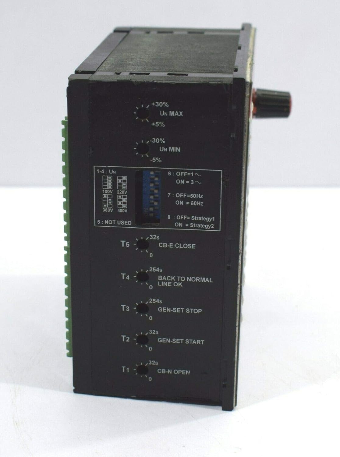
Figure 4: Side view with configuration settings.
- Voltage Selection (1-4 Un): Use dip switches to select the nominal voltage (e.g., 100V, 220V, 380V, 400V).
- Frequency Selection (7-8): Use dip switches to select the operating frequency (50Hz or 60Hz).
- Timers (T1-T5): Adjust these rotary knobs to set delays for:
- T1: CB-N Open delay
- T2: Gen-Set Start delay
- T3: Gen-Set Stop delay
- T4: Back to Normal Line OK delay
- T5: CB-E Close delay
5. Operating Instructions
The ATS010 operates automatically once configured. Manual controls are available for testing and specific operational modes.
5.1 Front Panel Controls and Indicators
- POWER ON (LED): Illuminates when the unit is receiving power.
- ATS Status (LED): Indicates the current status of the Automatic Transfer Switch.
- LOGIC ON/OFF (Button): Enables or disables the automatic transfer logic.
- RESET (Button): Resets any alarm conditions or manual overrides.
- Selector Knob (TEST/AUTOMATIC/Normal ON/Emer. OFF/Gen-Set START/Emergency ON):
- AUTOMATIC: Standard operating mode where the ATS automatically switches between normal and emergency power.
- TEST: Initiates a test sequence to verify ATS functionality.
- Normal ON: Forces the load to be supplied by the Normal Supply Line.
- Emer. OFF: Disconnects the Emergency Line.
- Gen-Set START: Manually starts the generator.
- Emergency ON: Forces the load to be supplied by the Emergency Line.
- Normal Supply Line Indicators (ON, ALARM, TRIP, WITHDR): Show the status of the normal power source and its circuit breaker.
- Emergency Line Indicators (ON, ALARM, TRIP, WITHDR): Show the status of the emergency power source and its circuit breaker.
- Generator Status Indicators (START, NOT AUTO, ALARM, NOT ENABLED): Provide feedback on the generator's operational state.
5.2 Automatic Operation
In AUTOMATIC mode, the ATS010 continuously monitors the Normal Supply Line. If the normal supply fails or falls outside acceptable parameters, the ATS will initiate a transfer sequence:
- Normal Supply Line failure detected.
- After a set delay (T1), the Normal Supply Line circuit breaker opens.
- After a set delay (T2), a signal is sent to start the emergency generator.
- Once the emergency generator reaches stable voltage and frequency, after a set delay (T5), the Emergency Line circuit breaker closes, supplying power to the load.
- When the Normal Supply Line is restored and stable, after a set delay (T4), the ATS will transfer the load back to the normal supply.
- After a set delay (T3), the emergency generator will shut down.
6. Maintenance
Regular maintenance ensures the longevity and reliable operation of the ATS010. Always disconnect all power before performing any maintenance.
- Visual Inspection: Periodically inspect the unit for any signs of damage, loose connections, or corrosion.
- Cleaning: Keep the unit clean and free of dust and debris. Use a dry, lint-free cloth. Do not use liquid cleaners.
- Functional Test: Perform a functional test using the "TEST" mode on the selector knob at least once every six months to ensure proper transfer operation.
- Terminal Tightness: Check and tighten all electrical connections annually to prevent overheating and intermittent operation.
7. Troubleshooting
This section provides basic troubleshooting steps. For complex issues, contact qualified service personnel.
| Problem | Possible Cause | Solution |
|---|---|---|
| Unit does not power on. | No input power; Blown fuse; Internal fault. | Check power supply to the unit; Inspect and replace fuses if necessary (by qualified personnel); Contact support. |
| ATS does not transfer to emergency power. | Emergency generator not starting; Generator output issues; ATS logic disabled; Incorrect timer settings. | Check generator operation; Verify generator output voltage/frequency; Ensure LOGIC ON/OFF is ON; Review timer settings (T2, T5). |
| ATS does not transfer back to normal power. | Normal supply not restored or unstable; Incorrect timer settings. | Verify normal power supply stability; Review timer settings (T4). |
| Alarm indicator is on. | System fault; Overload; Circuit breaker tripped. | Press RESET button; Identify and resolve the fault condition (e.g., reduce load); Check circuit breakers. |
8. Specifications
Key technical specifications for the ABB ATS010:
- Manufacturer: Isha Marine International (Seller) / ABB (Original Manufacturer)
- Model Number: ATS010
- ASIN: B07PW799ML
- Color: Black
- Size: Standard
- Number of Units: 1
- Connector Type: Quick Connection
- International Protection Rating: IP54
- First Available Date: August 14, 2019
9. Support Information
This product is listed as a salvaged item. For support, inquiries, or issues, please contact the seller directly through the platform where it was purchased.
Seller: Isha Marine International
Contact Method: Use the "Contact Seller" option on the product page of your purchase platform.
The seller states: "Responds instantly in 24 hours by Amazon message, worry-free service."