1. Introduction
This manual provides detailed instructions for the proper setup, operation, and maintenance of your DollaTek 28BYJ-48 ULN2003 5V Stepper Motor and Driver Board kit. Please read this manual thoroughly before use to ensure optimal performance and longevity of the product.
2. Product Overview
The DollaTek 28BYJ-48 ULN2003 kit consists of a unipolar stepper motor and a ULN2003 driver board. This combination is commonly used in various electronic projects requiring precise rotational control, such as robotics, automation, and DIY devices. The stepper motor operates by moving in discrete steps, controlled by the driver board which sequences current to its coils.
2.1 Components Included
- 5 x 28BYJ-48 5V Stepper Motor
- 5 x ULN2003 Driver Board

Figure 1: A 28BYJ-48 Stepper Motor connected to its ULN2003 Driver Board.
2.2 Key Features
- Stepper Motor: An electromagnetic device that moves in discrete steps.
- Coil Design: Features multiple coils and a central shaft with magnets, enabling rotation through magnetic attraction and repulsion.
- Unipolar Stepper Motor: The 28BYJ-48 is a unipolar motor with five wires and four coils, where center connections are tied together for power.
- Driver Board Indicators: A, B, C, D four-phase LEDs indicate the status of the stepper motor's operation.
- Standard Interface: Designed for direct plug-and-play use with common ULN2003 chip drivers and development boards.
3. Safety Information
- Ensure the power supply voltage matches the motor's rated voltage (DC 5V). Incorrect voltage can damage the motor or driver.
- Avoid touching electrical components while the system is powered on to prevent electric shock.
- Do not exceed the specified current limits for the motor and driver board.
- Keep the components away from moisture, dust, and extreme temperatures.
- Handle the motor and driver board with care to prevent physical damage.
4. Specifications
| Parameter | Value |
|---|---|
| Rated Voltage | DC 5V |
| Phase | 4-phase |
| Insulation Resistance | >10MΩ (500V) |
| Dielectric Strength | 600V AC / 1mA / 1s |
| Step Angle | 5.625° x 1/64 |
| DC Resistance | 200Ω ±7% (25°C) |
| Reduction Ratio | 1/64 |
| Insulation Grade | A |
| No-load Pull-in Frequency | >600Hz |
| No-load Pull-out Frequency | >1000Hz |
| Pull-in Torque | >34.3mN.m (120Hz) |
| Detent Torque | >34.3mN.m |
| Temperature Rise | <40K (120Hz) |
| Material | Metal |
| Weight | Approximately 207 Grams (for the kit) |
5. Setup and Connection
5.1 ULN2003 Driver Board Pinout
The ULN2003 driver board features several pins for power, motor connection, and microcontroller input. Understanding these pins is crucial for correct setup.
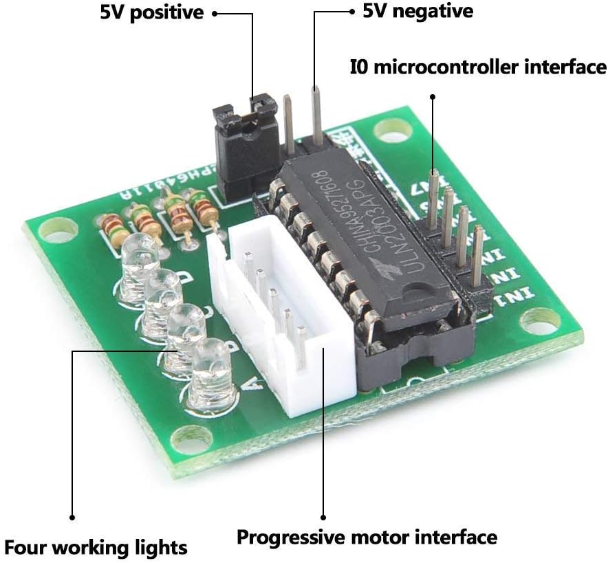
Figure 2: ULN2003 Driver Board with labeled connections.
- 5V Positive: Power input for the driver board (typically 5V DC).
- 5V Negative (GND): Ground connection for the driver board.
- IO Microcontroller Interface (IN1-IN4): These pins receive control signals from your microcontroller (e.g., Arduino) to drive the motor phases.
- Progressive Motor Interface: This is the 5-pin connector where the stepper motor's cable plugs in.
- Four Working Lights (LEDs): These LEDs illuminate to indicate which phase of the motor is currently active.
5.2 Connecting the Stepper Motor
The 28BYJ-48 stepper motor comes with a 5-wire connector. This connector is designed to directly plug into the 'Progressive Motor Interface' on the ULN2003 driver board. Ensure the connector is inserted firmly and in the correct orientation.
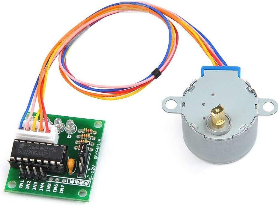
Figure 3: Stepper motor cable connected to the driver board.
5.3 Connecting to a Microcontroller
To control the stepper motor, connect the ULN2003 driver board to a microcontroller (e.g., Arduino, Raspberry Pi). The IN1, IN2, IN3, and IN4 pins on the driver board should be connected to digital output pins on your microcontroller. The 5V and GND pins on the driver board should be connected to the corresponding 5V and GND pins of your microcontroller's power supply.
- Connect ULN2003 IN1 to Microcontroller Digital Pin X
- Connect ULN2003 IN2 to Microcontroller Digital Pin Y
- Connect ULN2003 IN3 to Microcontroller Digital Pin Z
- Connect ULN2003 IN4 to Microcontroller Digital Pin W
- Connect ULN2003 5V to Microcontroller 5V
- Connect ULN2003 GND to Microcontroller GND
6. Operating Instructions
6.1 Basic Operation
The 28BYJ-48 is a unipolar stepper motor, meaning it has a common power connection for its coils. The ULN2003 driver IC contains Darlington transistor arrays that switch the current to the motor coils based on the input signals from the microcontroller. By sequentially energizing the coils, the motor shaft rotates in precise steps.
6.2 Control Sequence
To rotate the stepper motor, a specific sequence of signals must be sent to the IN1-IN4 pins of the ULN2003 driver board. Common stepping modes include full step, half step, and wave drive. The 28BYJ-48 typically uses a 4-phase sequence. Below is an example of a full-step sequence:
| Step | IN1 (Phase A) | IN2 (Phase B) | IN3 (Phase C) | IN4 (Phase D) |
|---|---|---|---|---|
| 1 | HIGH | LOW | LOW | LOW |
| 2 | LOW | HIGH | LOW | LOW |
| 3 | LOW | LOW | HIGH | LOW |
| 4 | LOW | LOW | LOW | HIGH |
By cycling through these steps, the motor will rotate. The speed of rotation is determined by the delay between each step. Reversing the sequence will reverse the motor's direction.
7. Maintenance
- Cleaning: Keep the motor and driver board free from dust and debris. Use a soft, dry cloth for cleaning. Avoid using liquids or solvents.
- Connections: Periodically check all electrical connections to ensure they are secure and free from corrosion.
- Operating Environment: Operate the motor within its specified temperature and humidity ranges to prevent damage.
- Physical Inspection: Inspect the motor shaft and gears for any signs of wear or obstruction. Ensure the motor is mounted securely.
8. Troubleshooting
| Problem | Possible Cause | Solution |
|---|---|---|
| Motor does not move | Incorrect wiring; Insufficient power; Incorrect control sequence; Damaged component. | Verify all connections (power, motor, microcontroller). Check power supply voltage (5V). Review your code for the correct stepping sequence. Test components individually if possible. |
| Motor vibrates but does not rotate | Incorrect stepping sequence; Motor phases not energized correctly. | Ensure the control sequence is correct for a 4-phase unipolar stepper motor. Check if all four working LEDs on the driver board are illuminating in sequence. |
| Motor rotates erratically or skips steps | Too high step speed; Insufficient current; Mechanical obstruction. | Reduce the step speed (increase delay between steps). Ensure the power supply can provide adequate current. Check for any physical obstructions preventing smooth rotation. |
| Driver board LEDs not lighting up | No power to driver board; No input signals from microcontroller. | Check 5V and GND connections to the driver board. Verify microcontroller is sending signals to IN1-IN4. |
9. Warranty and Support
DollaTek products are manufactured to high-quality standards. For any issues or technical support, please refer to the retailer or contact DollaTek customer service. Keep your purchase receipt for warranty claims, if applicable.