1. Introduction
This manual provides detailed instructions for the installation, operation, maintenance, and troubleshooting of the SEAFRONT SKI780 VFD Inverter Frequency Converter. This device is designed for precise motor speed control in various industrial and commercial applications. Please read this manual thoroughly before installation and operation to ensure safe and efficient use of the product.

Figure 1: General view of the SEAFRONT SKI780 VFD Inverter Frequency Converter.
2. Safety Information
Always observe the following safety precautions to prevent personal injury or damage to the equipment:
- Ensure that installation and wiring are performed by qualified personnel only.
- Disconnect all power sources before performing any wiring, maintenance, or inspection.
- Verify that the input voltage matches the specifications of the inverter.
- Do not touch electrical components immediately after power-off, as residual voltage may be present. Wait at least 5 minutes.
- Install the inverter in a clean, dry, and well-ventilated environment, away from direct sunlight, corrosive gases, and flammable materials.
- Ensure proper grounding of the equipment.
3. Product Overview
The SEAFRONT SKI780 VFD Inverter is a versatile device offering advanced control features for various motor applications.
Key Features:
- Integrated synchronous control and proportional timing control.
- Six speed control modes for automatic operation.
- Ability to lock all or part of the keys (analog potentiometer unlocked).
- Normally open relay and two high configuration outputs with 100 optional channels.
- Integrated user-defined counter/meter.
- 0-100% adjustable torque output at zero speed, with zero-speed brake function.
- V/F control and output torsion control.
- Integrated communication interface.
- Equipped with a speed potentiometer and an external panel.
- Five opto-isolated digital inputs, 100 optional channels.
- One analog input, two analog output channels.
- Textile pendulum frequency function, suitable for textile equipment.

Figure 2: Front view of the inverter showing the control panel and terminals.
4. Specifications
| Specification | Value |
|---|---|
| Model Number | SKI780-0D75G-1 |
| Brand | SEAFRONT |
| Input Voltage | 220 Volts (AC) |
| Output Voltage | 220 Volts (AC) |
| Output Power | 750 Watts |
| Peak Output Power | 1500 Watts |
| Inverter Power (VA) | 2200 VA |
| Output Waveform | Modified Sine Wave |
| Dimensions (L x W x H) | 14.2L x 11W x 8.5H centimeters (5.6 x 4.3 x 3.3 inches) |
| Number of Power Outlets | 1 |
| Power Source | Vehicle DC Power Socket (Note: Product description indicates AC input) |
| Country of Origin | China |
| GTIN/UPC | 736342831933 |

Figure 3: Dimensions of the SKI780 VFD Inverter.
5. Setup
Careful installation and wiring are crucial for the proper functioning of the VFD inverter.
5.1 Mounting
- Mount the inverter vertically on a stable, non-flammable surface.
- Ensure adequate clearance around the unit for proper ventilation and heat dissipation.
- Avoid mounting in areas with excessive vibration, dust, or moisture.
5.2 Wiring
Refer to the wiring diagram provided with your specific unit for detailed connections. General wiring steps include:
- Power Input (L, N): Connect the main AC power supply to the L and N terminals. Ensure correct voltage (220V AC).
- Motor Output (U, V, W): Connect the three-phase motor leads to the U, V, and W terminals.
- Grounding (PE): Connect the ground wire to the PE terminal for safety.
- Brake Resistor (P+, PB): If a brake resistor is used, connect it to the P+ and PB terminals.
- Control Terminals: Connect external control signals (digital inputs, analog inputs, relay outputs) to the respective terminals as per your application requirements.

Figure 4: Close-up of the inverter's terminal block for wiring connections.
5.3 External Panel Compatibility
If using an external control panel, ensure it is compatible with the inverter. The new panel design is specifically for new inverter models.

Figure 5: Correct connection of a new external panel to the inverter.
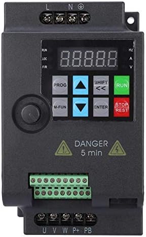
Figure 6: Incorrect connection of an old external panel to the inverter. Ensure panel compatibility.
6. Operating Instructions
The inverter features a control panel for setting parameters and operating the motor.
6.1 Control Panel Overview
The control panel typically includes:
- Display: Shows frequency, voltage, current, and other parameters.
- PROG Button: Enters/exits parameter setting mode.
- M-FUN Button: Multi-function button, often used for quick access to common functions.
- Up/Down Arrows: Navigate through menus and adjust parameter values.
- SHIFT/Left/Right Arrows: Move cursor or change digits during parameter entry.
- ENTER Button: Confirms selections and saves parameter changes.
- RUN Button: Starts the motor.
- STOP/RESET Button: Stops the motor or resets fault conditions.
6.2 Basic Operation
- Power On: Apply power to the inverter. The display will light up.
- Set Frequency: Use the Up/Down arrows or the external potentiometer to set the desired output frequency.
- Start Motor: Press the RUN button to start the motor. The motor will accelerate to the set frequency.
- Stop Motor: Press the STOP/RESET button to stop the motor. The motor will decelerate and stop.
6.3 Parameter Setting
To configure advanced settings:
- Press the PROG button to enter parameter setting mode.
- Use the Up/Down arrows to navigate through parameter groups and individual parameters.
- Press ENTER to select a parameter.
- Use the Up/Down arrows and SHIFT buttons to adjust the parameter value.
- Press ENTER to save the new value.
- Press PROG to exit parameter setting mode.
7. Maintenance
Regular maintenance ensures the longevity and reliable operation of your VFD inverter.
- Cleaning: Periodically clean the inverter's exterior and ventilation openings to prevent dust accumulation. Use a soft, dry cloth. Do not use liquid cleaners.
- Inspection: Regularly inspect wiring connections for tightness and signs of damage or corrosion. Check for any unusual noises or odors during operation.
- Cooling Fans: Ensure cooling fans are operating correctly and are free from obstructions. Replace noisy or faulty fans.
- Environmental Conditions: Verify that the operating environment remains within the specified temperature and humidity ranges.
- Capacitor Life: Electrolytic capacitors have a finite lifespan. Consider professional inspection and replacement after several years of continuous operation.
8. Troubleshooting
This section provides solutions to common issues you might encounter.
| Problem | Possible Cause | Solution |
|---|---|---|
| Inverter does not power on | No input power; Blown fuse; Faulty wiring | Check power supply; Replace fuse; Verify wiring connections. |
| Motor does not run | Incorrect parameters; Motor wiring error; Overload | Check frequency and control parameters; Verify motor wiring (U, V, W); Reduce motor load. |
| Overcurrent fault (OC) | Sudden load change; Short circuit in motor; Acceleration/deceleration time too short | Check motor and load; Increase acceleration/deceleration time parameters. |
| Overvoltage fault (OV) | Input voltage too high; Regeneration during deceleration | Check input voltage; Increase deceleration time; Install a brake resistor if necessary. |
| Undervoltage fault (UV) | Input voltage too low; Power supply instability | Check input voltage; Ensure stable power supply. |
| Overheat fault (OH) | Poor ventilation; Ambient temperature too high; Fan failure | Improve ventilation; Reduce ambient temperature; Check and replace cooling fan. |
For persistent issues or faults not listed, please contact technical support.
9. Support
For technical assistance, product inquiries, or service requests, please contact SEAFRONT customer support through your purchase channel or the official SEAFRONT website. Please have your model number (SKI780-0D75G-1) and serial number ready when contacting support.