Alomejor Alomejor6m2png581t-01
Alomejor 36V/48V 250W/350W Brushless Motor Controller LCD Panel Kit User Manual
Model: Alomejor6m2png581t-01
1. Introduction
This manual provides comprehensive instructions for the installation, operation, and maintenance of your Alomejor 36V/48V 250W/350W Brushless Motor Controller and LCD Panel Kit. This kit is designed to convert standard bicycles into electric bikes, offering enhanced speed control and real-time riding data. Please read this manual thoroughly before installation and use to ensure proper function and safety.
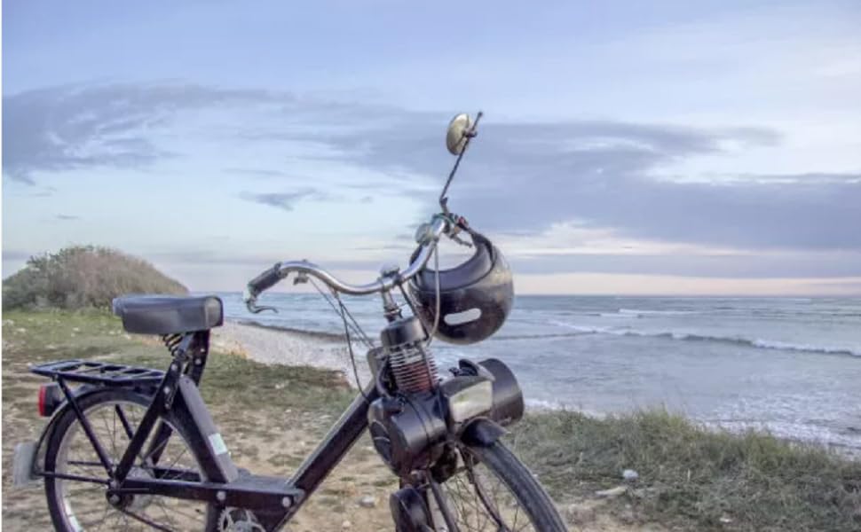
Figure 1.1: Example of an electric bike equipped with the conversion kit.
2. Package Contents
Verify that all components listed below are present in your package:
- Brushless Motor Controller (36V/48V, 250W/350W compatible)
- LCD Display Panel
- Throttle Grip (Twist Grip)
- Brake Levers (with power cut-off function)
- Pedal Assist Sensor (PAS)
- Associated Wiring Harnesses

Figure 2.1: Overview of included kit components.
3. Safety Information
Adhere to the following safety guidelines during installation and operation:
- Always wear a helmet and appropriate safety gear when riding an electric bike.
- Ensure all electrical connections are secure and properly insulated to prevent short circuits.
- Do not operate the electric bike in heavy rain or immerse components in water, as the LCD display is not fully waterproof.
- Regularly inspect brakes and tires for proper function and wear.
- Familiarize yourself with local regulations regarding electric bicycle use.
- Disconnect the battery before performing any maintenance or installation.
4. Installation and Wiring
Follow these steps for proper installation of the conversion kit. Refer to the wiring diagram for detailed connections.
4.1 Component Mounting
- Controller: Mount the brushless motor controller in a secure, well-ventilated location on your bike frame, away from direct water exposure. The aluminum shell with groove design aids in heat dissipation.
- LCD Display: Attach the LCD display panel to your handlebars in a position that is easily visible and accessible.
- Throttle Grip: Install the throttle grip on the right handlebar.
- Brake Levers: Replace your existing brake levers with the provided ones, ensuring they are securely fastened and the brake cables are properly connected.
- Pedal Assist Sensor (PAS): Install the PAS on the pedal crank, ensuring the sensor and magnet disc are correctly aligned.
4.2 Electrical Connections
Connect the components according to the wiring diagram below. Pay close attention to color-coded wires and connector types.
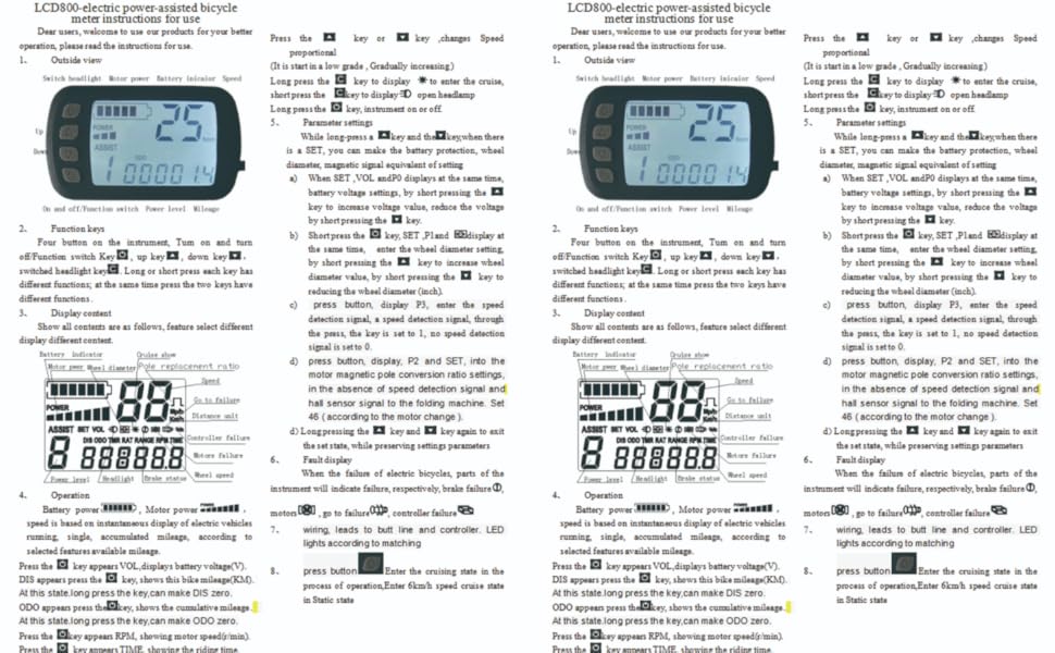
Figure 4.1: Comprehensive Wiring Diagram.
- Motor to Controller: Connect the motor phase wires (typically Green, Yellow, Blue) and Hall sensor wires to the corresponding connectors on the controller. If the motor runs in reverse, swap two of the motor phase wires (e.g., Controller Blue to Motor Yellow, Controller Yellow to Motor Green, Controller Green to Motor Blue).
- LCD Display to Controller: Connect the LCD panel's wiring harness to the designated port on the controller.
- Throttle to Controller: Connect the throttle grip to its respective controller port.
- Brake Levers to Controller: Connect the brake lever wires to the controller. These provide a power cut-off signal when brakes are applied.
- PAS to Controller: Connect the pedal assist sensor to the controller.
- Battery to Controller: Connect your 36V or 48V battery to the main power input of the controller. Ensure correct polarity.
After all connections are made, ensure they are secure and protected from moisture and physical damage.
5. Operating Instructions
This section details how to use your Alomejor LCD Panel and controller system.
5.1 Power On/Off
Press and hold the power button (U) on the LCD panel to turn the system on or off.
5.2 LCD Display Functions
The LCD panel provides real-time information:
- Riding Speed: Displays current speed in km/h or m/h.
- Battery Status: Indicates remaining battery charge.
- Power Assist Level: Shows the current level of motor assistance.
- Distance: Displays trip distance or total odometer.

Figure 5.1: Alomejor LCD Display Panel.
5.3 Adjusting Power Assist Levels
Use the UP (△) and DOWN (▽) buttons to cycle through different power assist levels. Higher levels provide more motor assistance.
5.4 Advanced Settings (P-Settings)
To access advanced settings, press and hold the UP and DOWN buttons simultaneously for a few seconds. Navigate through settings using the UP and DOWN buttons and confirm/enter with the C button.
- P0: Battery Voltage Cut-off: This setting typically defines the low voltage cut-off for the battery. For a 48V battery, this might be set around 42V. Incorrect setting can lead to inaccurate battery display.
- P1: Wheel Diameter: Set this to match your bike's wheel diameter (e.g., 26 inches). This affects speed and distance calculations.
- P2: Motor Poles: This setting calibrates the speed display based on your motor's pole count. Adjust by trial and error, comparing with a GPS speed reading.
- P3: Speed Unit: Toggle between kilometers per hour (km/h) and miles per hour (m/h).
- P4: (Function Varies): This setting's function can vary by firmware version. It may relate to cruise control or other advanced features.
After adjusting settings, press and hold the UP and DOWN buttons again to save and exit.
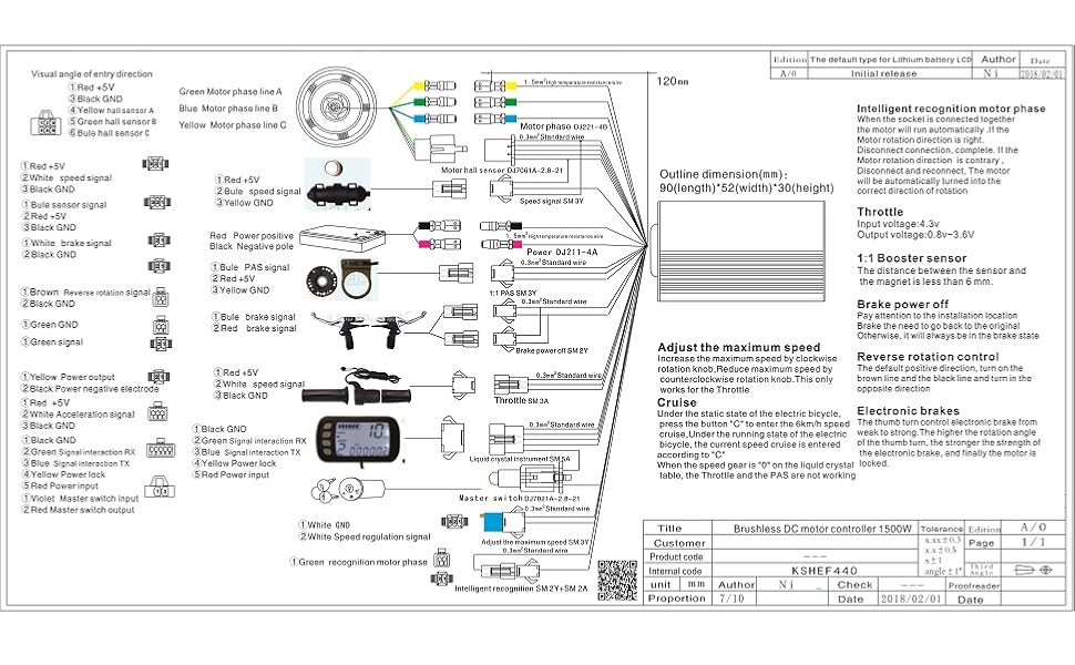
Figure 5.2: LCD display in use, showing readability in various conditions.
6. Maintenance
Proper maintenance ensures the longevity and reliable operation of your kit.
- Keep Connections Dry: Regularly check all electrical connections for moisture ingress. While the controller is designed for heat dissipation, prolonged exposure to water can damage components.
- LCD Display Care: The LCD display is not fully waterproof. Avoid exposing it to heavy rain or direct water spray. If water enters the display, carefully disassemble and dry the circuit board to prevent corrosion.
- Wiring Inspection: Periodically inspect all wires for fraying, cuts, or loose connections. Repair or replace damaged wiring immediately.
- Clean Components: Wipe down the controller and display with a dry or slightly damp cloth. Do not use harsh chemicals.
7. Troubleshooting
This section addresses common issues you may encounter.
| Problem | Possible Cause | Solution |
|---|---|---|
| Motor runs in reverse or does not run smoothly. | Incorrect motor phase wire connection. | Swap two of the motor phase wires (e.g., Green and Blue) between the motor and controller. |
| LCD display does not power on. | Loose connection, battery issue, or water ingress in display. | Check all connections. Ensure battery is charged. If exposed to water, dry the display's internal components. |
| Inaccurate speed or distance readings. | Incorrect P1 (wheel diameter) or P2 (motor poles) setting. | Access advanced settings (P-settings) and adjust P1 and P2 according to your bike's specifications and a GPS reference. |
| Throttle or pedal assist not working. | Loose connection, faulty sensor/throttle, or brake lever engaged. | Check connections for throttle and PAS. Ensure brake levers are not partially engaged, as they cut power. |
| System turns off unexpectedly. | Low battery voltage, loose battery connection, or controller overheating. | Charge battery. Check battery connections. Ensure controller has adequate ventilation. |
8. Specifications
| Feature | Detail |
|---|---|
| Brand | Alomejor |
| Model Number | Alomejor6m2png581t-01 |
| Controller Voltage | 36V / 48V (Auto-detect) |
| Motor Wattage Compatibility | 250W / 350W |
| Controller Material | Aluminum Alloy (with groove design for heat dissipation) |
| LCD Panel Material | Plastic |
| Special Features | Brushless Motor Controller, LCD Panel Kit, Speed Control, Battery Status, Power Assist Adjustment |
| Brake Style Compatibility | Disc Brake (levers included) |
| Drivetrain Type Compatibility | Hub Motor |
9. Warranty and Support
The Alomejor 36V/48V 250W/350W Brushless Motor Controller LCD Panel Kit comes with a limited warranty. For specific warranty terms, conditions, or technical support, please refer to the product packaging or contact Alomejor customer service directly. Keep your purchase receipt as proof of purchase.
Related Documents - Alomejor6m2png581t-01
 |
Cikada Touring EBike Service Manual Comprehensive service manual for the Cikada Touring EBike, covering general information, troubleshooting, parts dismounting/installation procedures, and maintenance. Includes detailed instructions and diagrams for servicing the electronic system, motor, console, and various bike components. |
 |
KB200 E-Bike Instructions - User Manual Comprehensive user manual for the KB200 children's electric balance bike, covering setup, operation, safety guidelines, maintenance, troubleshooting, and warranty information. |
 |
ADO E-Bike Air 28 Original Instructions Manual Official user manual for the ADO E-Bike Air 28, providing essential information on safety, operation, maintenance, troubleshooting, and warranty details for your electric bicycle. |
 |
ADO Air 20 Series Electric Bicycle User Manual This user manual provides essential information for the ADO Air 20 Series electric bicycle, covering setup, operation, safety guidelines, maintenance, and troubleshooting to ensure a safe and optimal riding experience. |
 |
Haoqi Leopard Pro Electric Bike Owner's Manual and Specifications Comprehensive guide for the Haoqi Leopard Pro (H1000) electric bike, covering assembly, operation, safety, maintenance, troubleshooting, and warranty. |
 |
Thule E-Flexi 958 Tow Bar Bike Carrier Instructions Detailed installation and usage instructions for the Thule E-Flexi 958 tow bar-mounted bike carrier. Includes safety guidelines, weight limits, compatibility checks, and step-by-step assembly and removal procedures. |