1. Introduction
The COMFAST CF-E113A is a high-power outdoor wireless WiFi bridge designed for long-range wireless data transmission. It operates in the 5.8GHz frequency band, offering enhanced stability and reduced interference compared to 2.4GHz devices. This device is suitable for various outdoor applications, including video surveillance backhaul and extending network coverage over distances up to 3 kilometers.

Image: The COMFAST CF-E113A Wireless WiFi Bridge, a white rectangular outdoor unit with the Comfast logo.
Its robust design ensures reliable operation in diverse outdoor environments, featuring dustproof and waterproof capabilities, and resistance to extreme temperatures.
2. Package Contents
Verify that all items listed below are present in your package:
- 1x CF-E113A WiFi Bridge
- 2x PoE Power Adapter
- 2x Stainless Steel Ties
- 1x User Manual (this document)

Image: Contents of the CF-E113A package, including the WiFi bridge unit, PoE adapters, stainless steel ties, and user manual.
3. Product Overview
The CF-E113A features a compact design with essential ports and indicators for easy setup and monitoring.

Image: Detailed view of the CF-E113A showing its components: Rotating Base, Indicator LEDs, Reset button, Toggle Switches (STA/AP), WAN port, LAN port, Cover, and Wire Holes.
Key Components:
- Rotating Base: For flexible mounting and angle adjustment.
- Indicator LEDs: Provide status information, including signal strength.
- Reset Button: Used to restore factory default settings.
- Toggle Switches (STA/AP): For configuring the device as a Station (client) or Access Point.
- WAN Port: Connects to the network source (e.g., router, NVR).
- LAN Port: Connects to local devices (e.g., IP camera, computer).
- Cover: Protects the ports from environmental elements.
- Wire Holes: For cable management and weather sealing.
4. Specifications
| Feature | Specification |
|---|---|
| Model | CF-E113A |
| CPU | Qualcomm AR9344 560MHz |
| Chipset | SKY85735 |
| Antenna | 11dBi Directional |
| WiFi Standard | IEEE 802.11a/an |
| Output Power | 200mW (23dBm) |
| Receiving Sensitivity | -96dBm |
| RF Frequency | 5.180GHz-5.825GHz |
| Transmission Rate | 300Mbps |
| Network Interface | 1x 10/100Mbps WAN + 1x LAN RJ45 Ethernet Port |
| Indicator | 8 LEDs |
| Power | 9-24V PoE Supply Power |
| Power Consumption | <8W |
| IP Index | IP65, 2KV Lightning protection |
| Installation | Wall-mounted, pole-mounted, bracket |
| Working Temperature | -40℃ ~ 55℃ |
| Storage Temperature | -55℃ ~ 75℃ |
| Working Humidity | 10% ~ 90%RH, non-condensing |
| Storage Humidity | 5% ~ 90%RH, non-condensing |
| Dimensions | 165 x 95 x 31 mm (6.5 x 3.74 x 1.22 inch) |

Image: The CF-E113A device highlighting its outdoor protection features against snow, rain, sun exposure, and frost, indicating its IP65 rating and ability to withstand extreme temperatures.
5. Setup and Installation
5.1. Physical Installation
The CF-E113A supports wall-mounted, pole-mounted, and bracket installations. Use the provided stainless steel ties for pole mounting or appropriate hardware for wall mounting.
Ensure the device is positioned with a clear line of sight to the other bridge unit(s) for optimal signal transmission.
5.2. Powering the Device
Connect the PoE power adapter to the WAN/LAN port of the CF-E113A and then plug the adapter into a power outlet. The device will power on automatically.
5.3. One-Click Pairing
The CF-E113A features a simplified pairing process for establishing a wireless bridge connection:
- Transmitter Setup: Set the toggle switch on the first CF-E113A unit to AP (Access Point) mode.
- Receiver Setup: Set the toggle switch on the second CF-E113A unit to STA (Station) mode.
- Pairing: The devices will automatically attempt to pair. A successful pairing will be indicated by specific LED patterns (refer to the LED indicator section in the full manual for details).
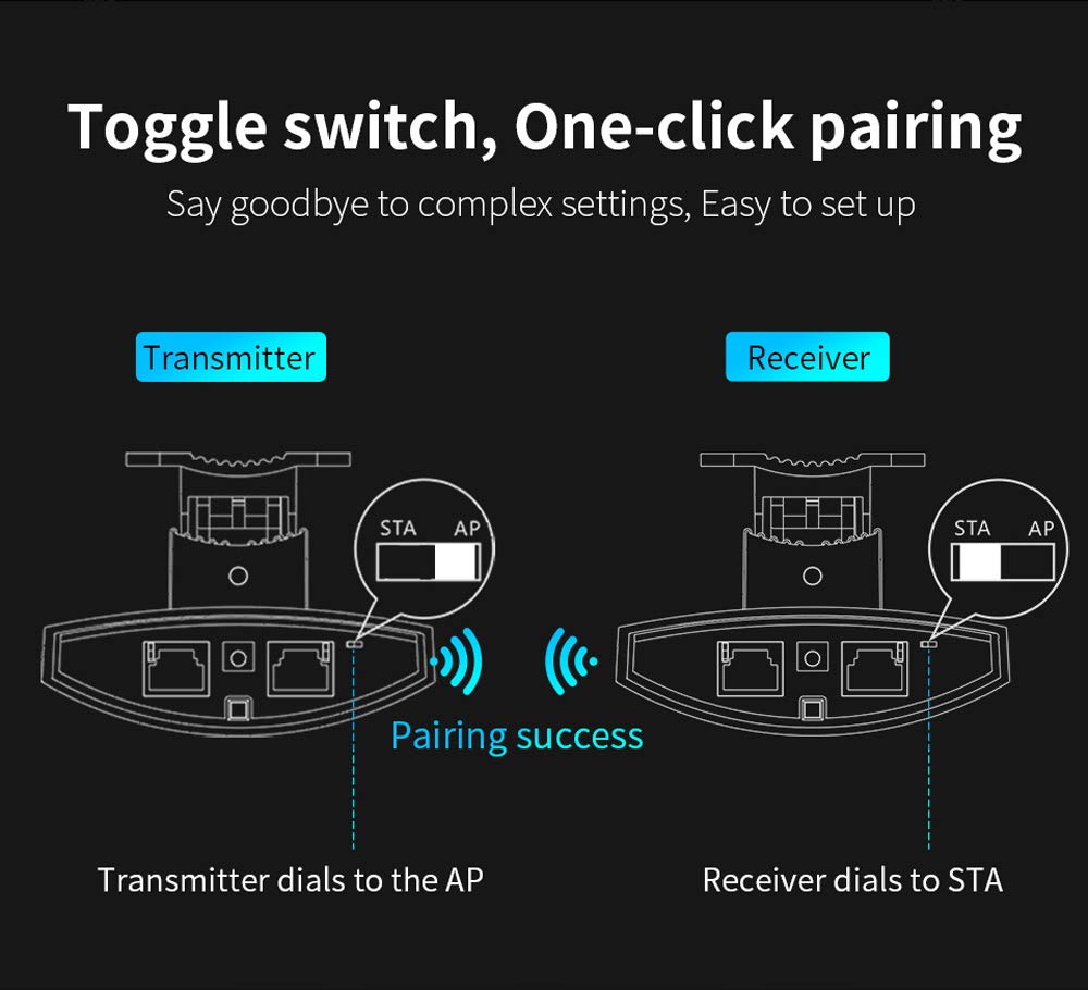
Image: Illustration of the one-click pairing process. One device is set to AP (Transmitter) and the other to STA (Receiver) using toggle switches, leading to a successful wireless connection.
5.4. Signal Alignment
After physical installation and initial pairing, optimize the signal strength by adjusting the angle of the CPE units. The device includes a signal strength indicator to assist with precise alignment.
- Very Strong: All indicator LEDs lit (e.g., green).
- Strong: Most indicator LEDs lit (e.g., green).
- General: Some indicator LEDs lit (e.g., red/orange).
- Weak: Few or no indicator LEDs lit (e.g., red).
Adjust the device angle until the signal strength indicators show the strongest possible connection.

Image: Close-up of the CF-E113A's signal strength indicator LEDs, showing how different levels of illumination correspond to signal quality (very strong, strong, general, weak).
6. Operating Modes
The CF-E113A can be configured for various wireless bridge scenarios.
6.1. Point-to-Point Connection
This is the most common setup, involving two CF-E113A units to create a direct wireless link between two locations. One unit acts as an Access Point (AP) and the other as a Station (STA).
6.2. Point-to-Multi-Point Connection
For scenarios requiring multiple remote locations to connect to a central point, one CF-E113A can act as an AP, and several other CF-E113A units can act as STAs. This is suitable for applications like distributed video surveillance.
Important: For optimal performance in a point-to-multi-point setup, ensure that the angle between the cameras/CPEs and the central monitoring CPE is less than 60 degrees. This configuration requires careful planning to meet broadband requirements and minimize signal degradation.

Image: Diagram illustrating a point-to-multi-point connection. Multiple cameras connected to individual CPEs transmit wirelessly to a central CPE, which then connects to an NVR and monitoring computer. The diagram emphasizes the 60-degree transmission angle requirement.
6.3. Example Application: Elevator Monitoring
The CF-E113A can be used to establish wireless links for elevator monitoring systems, providing connectivity between cameras inside elevators and a central security and monitoring center. This eliminates the need for complex wiring within elevator shafts.

Image: Two diagrams showing different ways to implement elevator monitoring using wireless CPEs. Both methods connect cameras within elevators wirelessly to a central security and monitoring center.
7. Maintenance
The COMFAST CF-E113A is designed for minimal maintenance due to its robust outdoor casing. However, periodic checks can ensure optimal performance:
- Physical Inspection: Periodically inspect the device and its mounting for any signs of damage, loose connections, or obstruction to the line of sight.
- Cleaning: If necessary, gently clean the exterior of the device with a soft, damp cloth. Do not use harsh chemicals or abrasive materials.
- Firmware Updates: Check the official COMFAST website for any available firmware updates. Keeping the firmware updated can improve performance, stability, and security.
- Environmental Conditions: Ensure the device remains within its specified operating temperature and humidity ranges.
8. Troubleshooting
This section addresses common issues you might encounter with your CF-E113A WiFi Bridge.
8.1. No Power
- Ensure the PoE adapter is correctly connected to the device and a working power outlet.
- Verify that the power outlet is functional.
- Check the Ethernet cable connecting the PoE adapter to the CF-E113A for damage.
8.2. No Wireless Connection / Poor Signal
- Line of Sight: Ensure there is a clear, unobstructed line of sight between the two bridge units. Obstacles like trees, buildings, or hills can severely degrade signal quality.
- Alignment: Re-adjust the angle of both CF-E113A units using the signal strength indicators to achieve optimal alignment.
- Mode Setting: Confirm that one unit is set to AP mode and the other to STA mode using the toggle switches.
- Interference: The 5.8GHz band is less prone to interference than 2.4GHz, but other 5.8GHz devices or strong electromagnetic sources could still cause issues. Try repositioning the devices slightly if possible.
- Distance: While rated for 3km, extreme weather or environmental factors can affect maximum range. Ensure the distance is within reasonable limits for your specific environment.
8.3. Network Connectivity Issues (After Wireless Link is Established)
- Cable Connections: Check all Ethernet cables connecting the CF-E113A units to your network devices (router, NVR, PC).
- IP Address Conflict: If you have manually configured IP addresses, ensure there are no conflicts on your network.
- Router/NVR Settings: Verify that your connected router or NVR is properly configured and functioning.
8.4. Resetting to Factory Defaults
If you encounter persistent issues or forget your configuration settings, you can reset the device to its factory defaults using the Reset button. Typically, this involves pressing and holding the Reset button for 5-10 seconds while the device is powered on, then releasing it. Refer to the full product manual for the exact procedure.
9. Warranty and Support
The COMFAST CF-E113A typically comes with a 1-Year Warranty from the date of purchase. This warranty covers manufacturing defects and malfunctions under normal use conditions.
For technical support, warranty claims, or further assistance, please contact your retailer or visit the official COMFAST website for contact information and support resources.
Please retain your proof of purchase for warranty validation.