1. Introduction and System Overview
This manual provides detailed instructions for the installation, operation, and maintenance of the YAVIS Full Set RFID Access Control System Kit (Model K2000+180KG). This system is designed for single-door access control, offering secure entry via RFID cards, passwords, or a combination of both. Please read this manual thoroughly before installation and operation to ensure proper functionality and safety.
The complete kit includes the following main components:
- K2000 Access Control Keypad
- K80 Power Supply
- 180kg Electric Magnetic Lock
- Door Exit Button
- 10 RFID Keyfobs
2. Product Components and Features
2.1 K2000 Access Control Keypad
The K2000 is a standalone access controller that supports up to 500 users. It allows access through RFID cards, passwords, or a combination of both. Programming is performed directly from the keypad, eliminating the need for a computer connection.
- Voltage: 12V DC
- Current: 120 mA
- User Capacity: 500 users
- Proximity Reader Frequency: 125 kHz
- Compatible Cards: EM or EM compatible cards
- Open Modes: Card, Password, Card + Password
- Dimensions: 118 x 118 x 22 mm
- Material: Plastic

Figure 2.1: K2000 Access Control Keypad. This image shows the K2000 keypad with a hand holding an RFID card near the reader and another hand pressing a number on the keypad. The display indicates 'POWER' and 'OK' status lights.
2.2 K80 Power Supply
The K80 power supply converts AC input to stable DC 12V output for the access control system. It features automatic protection against short circuits.
- AC Input: 100V-240V (50-60Hz, 36W)
- DC Output: 12V/3A
- Outputs: NC / NO for various electric locks
- Protection: Automatic short-circuit protection
- Dimensions: 140 x 67 x 33 mm (approximate, based on image)

Figure 2.2: K80 Power Supply. This image displays the K80 power supply unit with its input/output terminals and approximate dimensions labeled.
2.3 180kg Electric Magnetic Lock
This magnetic lock provides a strong holding force of 180kg. It operates in NC (Normally Closed) mode, meaning it is locked when powered on and unlocks automatically when power is removed (fail-safe). It is waterproof and includes an integrated voltage suppressor.
- Operating Voltage: DC 12V
- Operating Current: 380-500 mA
- Holding Force: 180 kg
- Mode: NC (Fail-safe: unlocked when power off, locked when power on)
- Features: Integrated voltage suppressor, waterproof, no LED indicator
- Dimensions: 170 x 23 x 39 mm (main body) / 130 x 33 x 9.3 mm (armature plate)
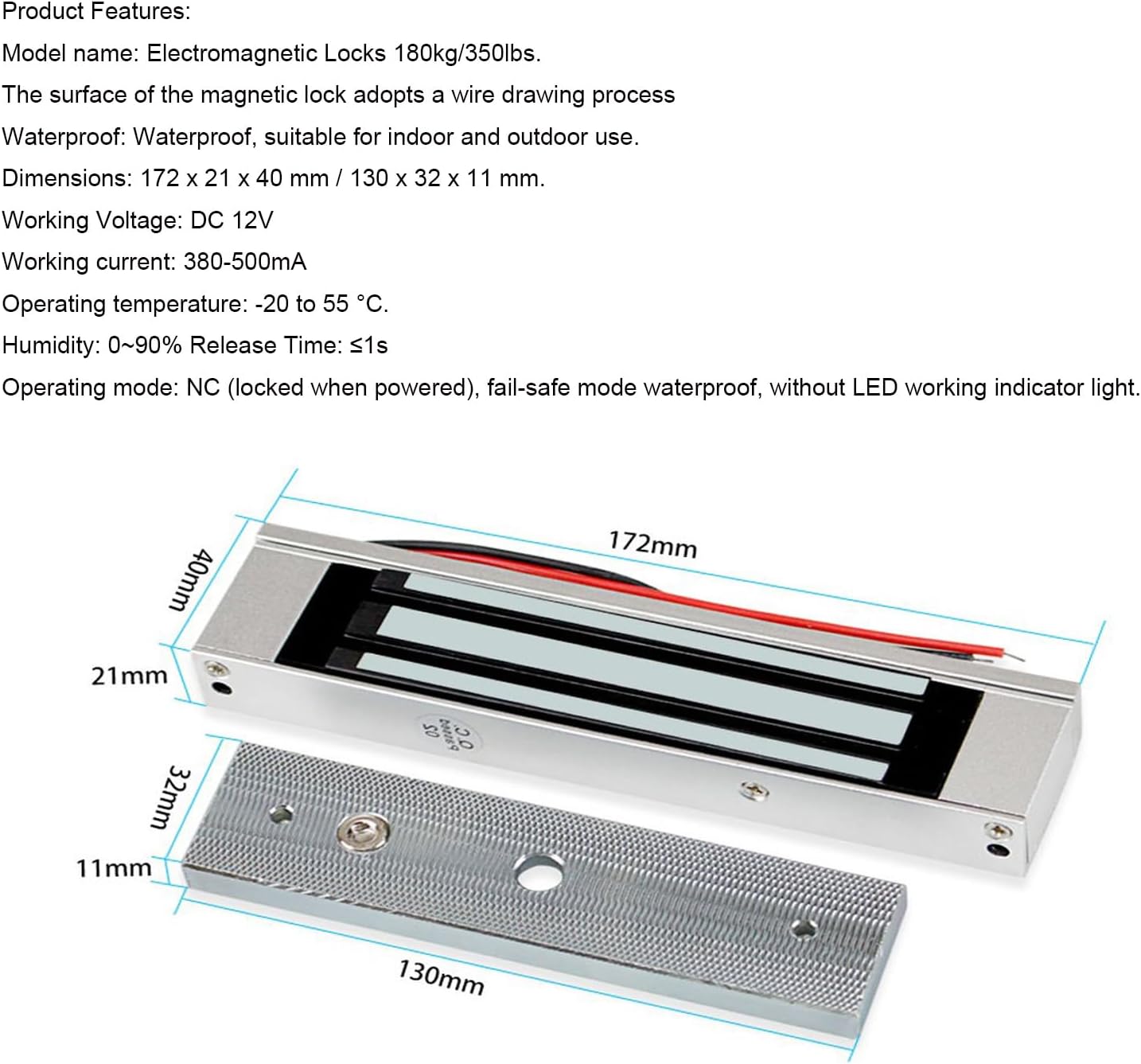
Figure 2.3: 180kg Electric Magnetic Lock. This image shows the magnetic lock components, including the main lock body and the armature plate, with their respective dimensions.
2.4 Door Exit Button
A simple push-button for exiting the controlled area. Made from flame-retardant ABS plastic.
- Material: ABS flame-retardant plastic
- Output Contact: NO / COM
2.5 RFID Keyfobs
The kit includes 10 blue RFID keyfobs for convenient access. These are read-only and operate at 125 KHz.
- Frequency: 125 KHz
- Chip Type: TK4100
- Color: Blue
- Function: Read-only
- Quantity: 10 pieces

Figure 2.4: RFID Keyfobs. This image shows a set of blue RFID keyfobs, which are used for access control.
3. Setup and Installation
Proper installation is crucial for the reliable operation of your access control system. It is recommended that installation be performed by a qualified technician. Refer to the wiring diagram below for connection details.
3.1 Component Placement
Strategically place each component for optimal functionality and security:
- Access Controller (K2000): Mount on the wall near the door, on the secure side, at a convenient height for users.
- Magnetic Lock: Install on the door frame and door leaf according to the lock's specific instructions. Ensure proper alignment for maximum holding force.
- Power Supply: Mount in a secure, dry location, preferably near the access controller or a power outlet.
- Exit Button: Install on the secure side of the door, allowing easy exit.

Figure 3.1: System Component Placement. This image illustrates the typical installation of the access controller, magnetic lock, power supply, and exit button on and around a door.
3.2 Wiring Diagram
Follow the wiring diagram carefully to connect all components. Incorrect wiring can damage the system or prevent it from functioning.

Figure 3.2: Wiring Diagram. This diagram shows the electrical connections between the K2000 access controller, K80 power supply, magnetic lock, and exit button.
Key Wiring Points:
- Connect the K80 Power Supply AC input to a standard 100-240V AC source.
- Connect the DC 12V output from the K80 Power Supply to the K2000 Access Controller and the Magnetic Lock.
- Ensure the Magnetic Lock is connected to the appropriate NC/NO terminals on the power supply or controller based on its operating mode (NC for fail-safe).
- Connect the Exit Button to the PUSH/NO and COM terminals on the K2000 Access Controller.
- Verify all connections are secure and insulated.
4. Operating Instructions
4.1 K2000 Keypad Operation
The K2000 keypad allows for direct programming and user management. Refer to the specific programming guide included with the K2000 for detailed steps on:
- Changing the master password.
- Adding new user RFID cards.
- Adding new user passwords.
- Adding users with card + password access.
- Deleting existing users.
- Adjusting door release time (0-15 seconds).
To gain access, present an enrolled RFID card to the reader, enter a valid password, or use the card + password combination as programmed.
4.2 Exit Button Usage
To exit the controlled area, simply press the Door Exit Button. This will momentarily release the magnetic lock, allowing the door to open.
5. Maintenance
Regular maintenance ensures the longevity and reliable performance of your access control system:
- Cleaning: Regularly clean the surface of the K2000 keypad and the magnetic lock with a soft, dry cloth. Avoid abrasive cleaners or solvents.
- Wiring Inspection: Periodically check all wiring connections for tightness and signs of wear or damage. Ensure all connections are secure.
- Magnetic Lock: Ensure the magnetic lock and its armature plate are free from dirt, debris, or obstructions that could prevent proper locking.
- Environmental Protection: Avoid exposing components to extreme temperatures, direct sunlight, or excessive moisture beyond their specified operating conditions.
- Functionality Test: Periodically test the system's functionality, including card access, password access, and the exit button, to ensure all components are working correctly.
6. Troubleshooting
If you encounter issues with your YAVIS Access Control System, refer to the following troubleshooting guide:
| Problem | Possible Cause | Solution |
|---|---|---|
| System not powering on | No power to the K80 Power Supply; faulty wiring. | Check AC input to the power supply. Verify all power connections are secure. |
| Door not locking/unlocking | Incorrect wiring to magnetic lock; power supply issue; magnetic lock malfunction. | Review wiring diagram (Figure 3.2). Ensure NC/NO settings are correct for the magnetic lock. Check power supply output. |
| RFID card not granting access | Card not enrolled; incorrect card type/frequency; card damaged. | Ensure the card is properly enrolled in the K2000 system. Verify card frequency (125 KHz) and type (EM compatible). Try a different enrolled card. |
| Keypad not responding | No power to K2000; physical damage; internal fault. | Check power connection to the K2000. Inspect for visible damage. If issues persist, contact support. |
| Exit button not working | Incorrect wiring of the exit button; faulty button. | Verify the exit button is correctly wired to the PUSH/NO and COM terminals on the K2000. Test the button for continuity if possible. |
If the problem persists after attempting these solutions, please contact YAVIS customer support for further assistance.
7. Specifications
| Component | Specification |
|---|---|
| K2000 Access Controller |
|
| K80 Power Supply |
|
| 180kg Electric Magnetic Lock |
|
| RFID Keyfobs |
|
| Overall Product Dimensions | 2 x 2 x 2 cm; 1.7 kilograms (packaging dimensions) |
8. Warranty and Support
The YAVIS Full Set RFID Access Control System Kit comes with a 1-year warranty and lifetime support.
For technical assistance, troubleshooting not covered in this manual, or warranty claims, please contact YAVIS customer service through your purchase platform or the official YAVIS website. Please have your product model number (K2000+180KG kit) and purchase details ready when contacting support.